
Wire-cutting waste wire collecting device

A collecting device and wire cutting technology, which is applied in the direction of accessory devices, electric processing equipment, metal processing equipment, etc., can solve the problems of unstable feeding, inconsistent tightness of electrode wires, large space, etc., to avoid fluffy occupation of space and design structure Simple and practical, the effect of improving collection efficiency

Inactive Publication Date: 2015-08-05
SUZHOU INST OF TRADE & COMMERCE
View PDF5 Cites 4 Cited by
  • Summary
  • Abstract
  • Description
  • Claims
  • Application Information

AI Technical Summary

Problems solved by technology

[0003] 1. As the processing time increases, the diameter of the electrode wire will become thinner due to electric corrosion until the wire is broken;
[0004] 2. The coolant cannot enter the slit during processing, and the electrode wire cannot be cooled sufficiently and is blown;
[0006] 4. The tightness of the electrode wire on the wire barrel is inconsistent or the guide wheel and bearing are worn out, and the radial runout is large, causing the local wire to shake violently and break the wire;
[0007] 5. If the feed is too fast or too slow, it will cause instability and cause broken wires;
[0008] 6. When the workpiece is cut, it falls and breaks the electrode wire
The current method of removing waste wire is that workers manually wind the wire from the wire drum in a manner similar to that of winding wool balls. However, because the diameter of the electrode wire is small, it is no less than a sharp knife under pressure. Without safety measures It is very easy to injure the fingers or even cut off the fingers
The waste silk wound by hand is often a large fluffy group, which not only takes up a lot of space, but also may cause personal injury to others

Method used


Image

  • Wire-cutting waste wire collecting device
  • Wire-cutting waste wire collecting device
  • Wire-cutting waste wire collecting device

Examples


Embodiment Construction

[0025] In order to make the above objects, features and advantages of the present invention more comprehensible, specific implementations of the present invention will be described in detail below in conjunction with the accompanying drawings. It should be noted that all the drawings of the present invention are in simplified form and use inaccurate scales, and are only used to facilitate and clearly assist the purpose of illustrating the embodiments of the present invention.

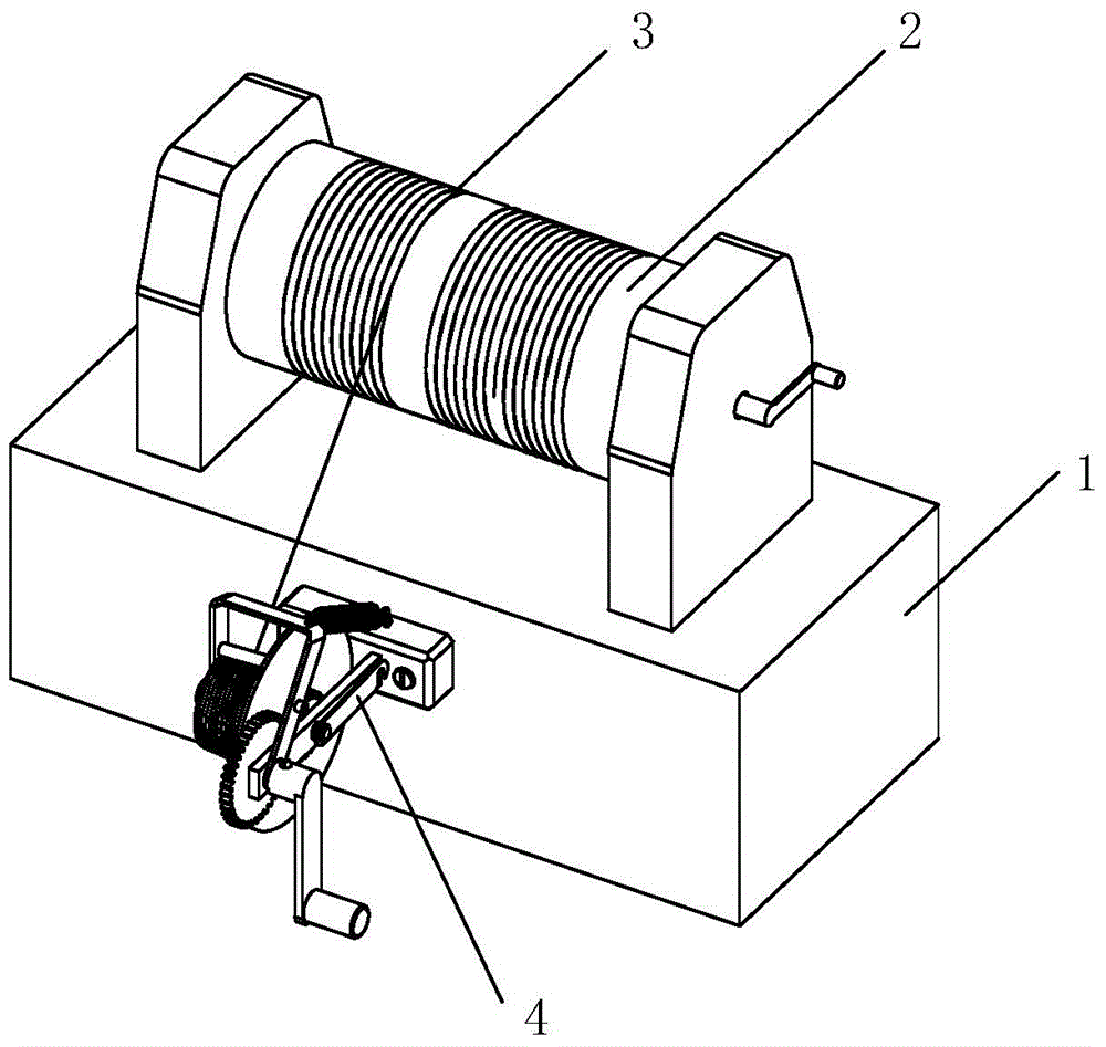
[0026] Such as figure 1 As shown, the wire cutting waste wire collection device 4 of the present invention can be installed at any suitable position of the wire electric discharge machine tool, and the wire electric discharge machine tool includes: a bed 1, a wire bucket 2 installed on the bed 1 and The waste wire 3 on the wire barrel 2 is generally installed at any suitable position of the bed 1 by the wire cutting waste wire collection device 4 of the present invention.

[0027] Such as Figure 2 to...


PUM


Abstract

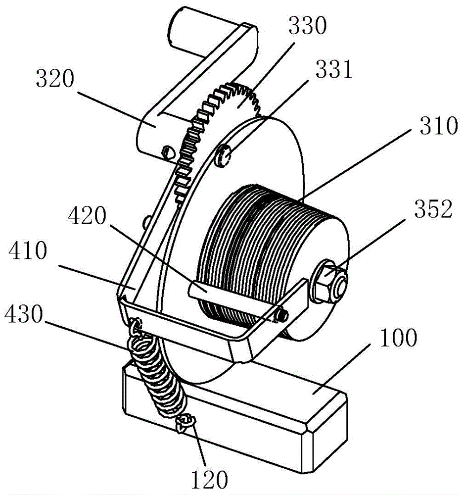
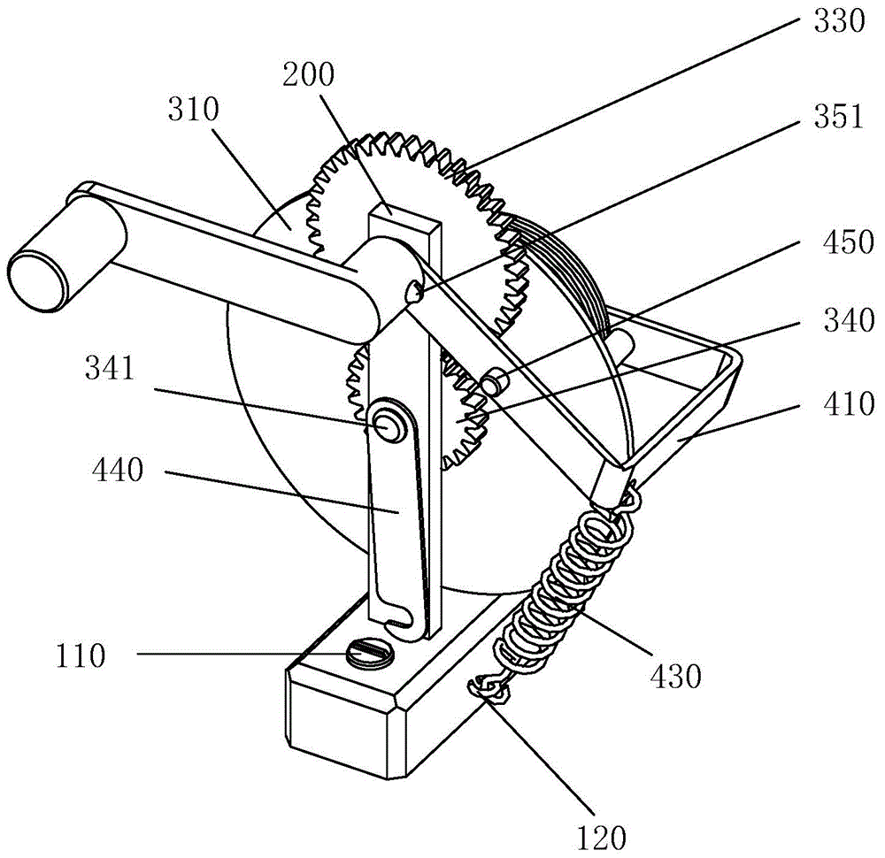
The invention discloses a wire-cutting waste wire collecting device which comprises a base, a support, a material-collecting mechanism and a wire pressing mechanism, wherein the base is installed at the random position of a electrospark wire-cutting machine tool; the support is vertically installed on the base; the material-collecting mechanism comprises a collecting drum and a handle which are installed on the two sides of the support respectively, and the handle drives the collecting drum to rotate through a gear module. The wire pressing mechanism comprises a wire pressing piece, a roller and a tension spring. One end of the wire pressing piece is hinged to a large gear shaft on the support, the other end of the wire pressing piece adheres to the end of the collecting drum, and the roller is fixed on the wire pressing piece and adheres to the side of the collecting drum. One end of the tension spring is fixedly connected with the wire pressing piece, and the other end of the tension spring is fixedly connected with the base. Through the use of the wire-cutting waste wire collecting device, after the wire breakage occurs, a waste wire on a wire drum is tightly wound around the collecting drum through the wire pressing mechanism; and the waste wire is small in occupied space and easy to accommodate.

Description

technical field [0001] The invention relates to a wire electric discharge machine tool, in particular to a wire cutting waste wire collection device applied to the wire electric discharge machine tool. Background technique [0002] Broken wire has always been a serious problem in the process of WEDM processing, it makes the processing stop and has to start from scratch, destroys the integrity of the processing surface, it is difficult to realize unmanned operation processing, and it is wasteful to replace the new wire A lot of working hours, after research, the broken wire mainly has the following reasons: [0003] 1. As the processing time increases, the diameter of the electrode wire will become thinner due to electric corrosion until the wire is broken; [0004] 2. The coolant cannot enter the slit during processing, and the electrode wire cannot be cooled sufficiently and is blown; [0005] 3. There are slag inclusions in the blank, the surface is covered with oxides, ...

Claims


Application Information

Patent Timeline
IPC IPC(8): B23H11/00
CPCB23H11/00
Inventor 郭秀华
Owner SUZHOU INST OF TRADE & COMMERCE
Learn More