Supercharge Your Innovation With Domain-Expert AI Agents!

Vibrating feeder with selectable conveying direction

A technology of vibrating feeder and conveying direction, which is applied in the direction of conveyor, vibrating conveyor, transportation and packaging, etc. It can solve the problems of wasting resources, troublesome operation, occupying space, etc., and achieves the advantages of convenient conversion, space saving and resource saving Effect

Inactive Publication Date: 2013-04-17
XINXIANG GAOFU MACHINERY CO LTD
View PDF6 Cites 0 Cited by
  • Summary
  • Abstract
  • Description
  • Claims
  • Application Information

AI Technical Summary

Problems solved by technology

This not only wastes resources, but also takes up space, and the operation is troublesome

Method used


Image

  • Vibrating feeder with selectable conveying direction

Examples


Embodiment Construction

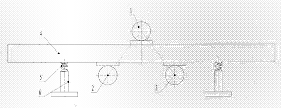
[0008] The embodiment is described in detail with reference to the accompanying drawings. It includes a support 6 on which a horizontal conveying trough 4 is installed with a damping spring 5. The improvement is that a horizontal master is installed upwards in the middle of the top of the conveying trough. The vibration motor 1 is parallel to the axis of the main vibration motor on the bottom surface of the conveying trough, and the rotation direction is opposite, and two vibration-assisting motors 2 and 3 are installed on the left and right in a square shape. When installing, just install a power switch connected to various motors on the console, and install a selector switch on the power cord, which direction the selector switch needs to be conveyed in, so that the side of the vibration aid The main vibration motor works synchronously with the main motor, and the vibration-assisting motor on the other side stops. To meet the design requirements, the operation conversion is ve...


PUM


Abstract

The invention discloses a vibrating feeder with the selectable conveying direction. The vibrating feeder comprises a supporting seat, a horizontal conveying trough is mounted on the supporting seat through a damper spring, a horizontal main vibrating motor is upwardly mounted in the middle of the top of the conveying trough, and a left auxiliary vibrating motor and a right auxiliary vibrating motor which are axially parallel to the main vibrating motor and opposite in rotation direction are mounted on the bottom face of the conveying trough in a triangular form. The vibrating feeder has the advantages of saving of resources and places and convenience in shifting of the conveying directions.

Description

[0001] Technical field: [0002] The invention relates to conveying, in particular to a vibrating feeder with a selectable conveying direction. Background technique: [0003] The current vibrating feeder has a structure where a conveying trough is installed on a support with a shock-absorbing spring, and two synchronous vibration motors with the same rotation direction are installed on the conveying trough in parallel and symmetrically. This traditional vibrating feeder can only be turned from the motor to vibrate feeding and conveying from one end to the other end. If the conveying direction needs to be changed, it is necessary to install a vibrating feeder with the opposite conveying direction. This wastes resources, takes up space, and is troublesome to operate. Summary of the invention: [0004] The purpose of the present invention is to provide a vibrating feeder which can select the conveying direction of materials to any end with one feeder. [0005] The technical schem...

Claims


Application Information

Patent Timeline
Patent Type & Authority Applications(China)
IPC IPC(8): B65G27/32
Inventor 荆素中崔立达王明利
Owner XINXIANG GAOFU MACHINERY CO LTD
Features
  • R&D
  • Intellectual Property
  • Life Sciences
  • Materials
  • Tech Scout
  • Unparalleled Data Quality
  • Higher Quality Content
  • 60% Fewer Hallucinations
Learn More