Displacement sensor for detecting spherical motion

A displacement sensor and spherical motion technology, applied in the field of displacement sensors, can solve problems such as inconvenient installation and complex structure, and achieve the effect of convenient detection and simple structure

Active Publication Date: 2013-04-17
SHENZHEN UNIV
View PDF4 Cites 3 Cited by
  • Summary
  • Abstract
  • Description
  • Claims
  • Application Information

AI Technical Summary

Problems solved by technology

In order to detect the relative displacement of the inner and outer spherical surfaces, it is generally necessary to set up a sensor for l

Method used


Image

  • Displacement sensor for detecting spherical motion
  • Displacement sensor for detecting spherical motion
  • Displacement sensor for detecting spherical motion

Examples


Embodiment Construction

[0021] The present invention will be further described in detail below through specific embodiments in conjunction with the accompanying drawings.

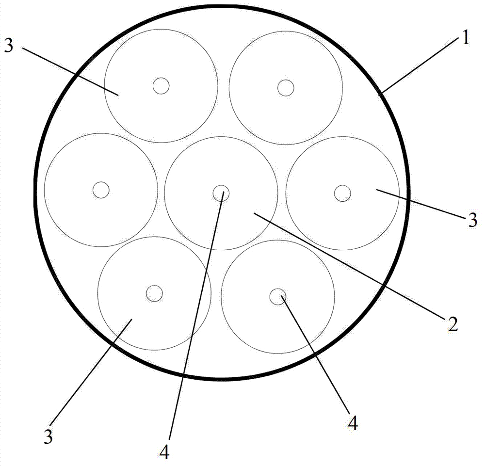
[0022] The displacement sensor used to detect spherical motion has a group of optical fibers. The group of optical fibers is arranged in a cylindrical shape. One optical fiber in the middle outputs laser light, and the other optical fibers receive laser light. According to the intensity variation of the laser signal received by each optical fiber, the internal , The direction and displacement of the relative movement of the outer spherical surface, and then calculate the velocity and acceleration.

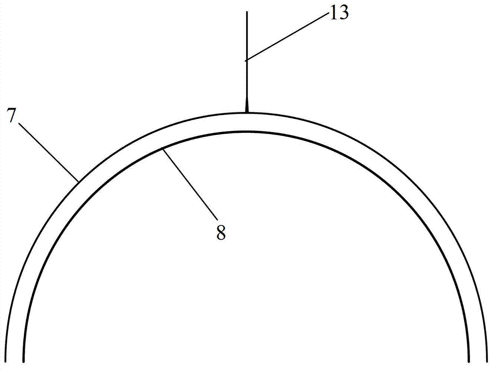
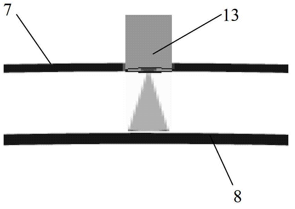
[0023] Such as Figure 1 to Figure 5 As shown, the displacement sensor 13 in this embodiment is used to detect the relative displacement between the outer spherical surface and the inner spherical surface. The displacement sensor comprises an optical fiber coating layer 1 and a first optical fiber 2 and a plurality of second optical f...


PUM


Abstract

The invention discloses a displacement sensor for detecting spherical motion. The displacement sensor comprises a fiber coating layer, and a first fiber and a plurality of second fibers which are arranged in the fiber coating layer; the second fibers enclose the first fiber; the first fiber outputs laser; and each second fiber receives the laser. The displacement sensor can conveniently detect the displacement of the relative motion of a spherical surface easily and has a simple structure.

Description

technical field [0001] The invention relates to a displacement sensor for detecting the relative movement of inner and outer spherical surfaces. Background technique [0002] The detection of the relative movement of the spherical surface is more complicated, and the outer spherical surface and the inner spherical surface can produce relative latitude displacement and longitude displacement. In order to detect the relative displacement of the inner and outer spherical surfaces, it is generally necessary to set up a separate sensor for detecting latitude displacement and a separate sensor for longitude displacement, which is not only complicated in structure, but also inconvenient to install. Contents of the invention [0003] The invention provides a new displacement sensor for detecting spherical motion. [0004] The present invention provides a displacement sensor for detecting spherical motion, which includes an optical fiber coating layer and a first optical fiber and...

Claims


Application Information

Patent Timeline
IPC IPC(8): G01B11/02G01D5/353
Inventor 秦斌杜戈果禹世杰
Owner SHENZHEN UNIV
Why Eureka
Try Eureka