A displacement detection device and equipment having the device

A displacement detection and equipment technology, applied in the field of medical devices, can solve the problems of high installation accuracy, limited detection stroke, low detection accuracy, etc., and achieve controllable equipment processing and assembly accuracy, high measurement accuracy, and affordable manufacturing costs. control effect

Active Publication Date: 2021-12-03
SHANGHAI NEUSOFT MEDICAL TECH LTD +1
View PDF7 Cites 0 Cited by
  • Summary
  • Abstract
  • Description
  • Claims
  • Application Information

AI Technical Summary

Problems solved by technology

[0003] At present, the position detection methods of the scanning bed are mainly divided into two categories: one is to directly detect the position of the bed board carrying the patient. This detection method belongs to a fully closed-loop structure and can achieve relatively high actual position feedback accuracy. The specific detection method Including pull rope encoders, grating rulers and other structures; however, limited by their own structural principles, the above two detection devices have problems such as limited detection travel, high cost, and high installation accuracy requirements
Another way is to detect a certain link in the transmission chain, such as using a rotary encoder to detect a certain rotating link in the transmission chain. Through the calculation of the transmission ratio, it is equivalent to the horizontal displacement of the bed board, which has the characteristics of relatively low cost. However, the detection object of this detection principle is the intermediate link in the transmission chain, which belongs to the semi-closed loop structure. There are usually factors such as gaps and manufacturing assembly errors in the transmission chain, resulting in relatively low final detection accuracy.

Method used


Image

  • A displacement detection device and equipment having the device
  • A displacement detection device and equipment having the device
  • A displacement detection device and equipment having the device

Examples


Embodiment Construction

[0031] In order to enable those skilled in the art to better understand the technical solutions of the present invention, the present invention will be further described in detail below in conjunction with the accompanying drawings and specific embodiments.

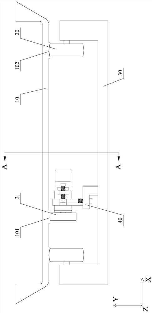
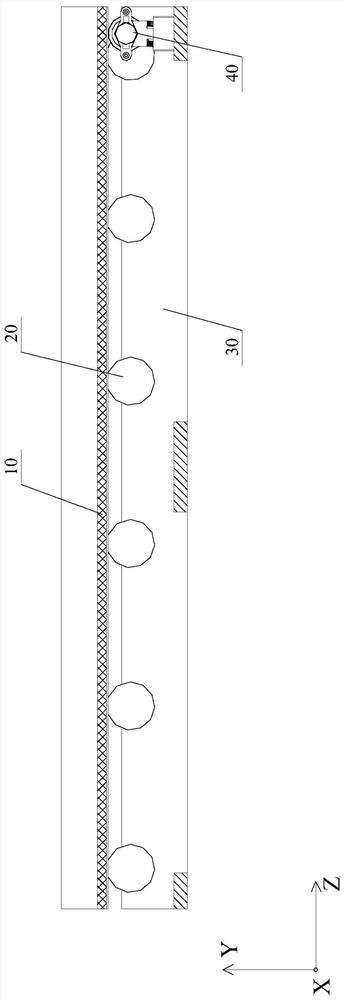
[0032] Without loss of generality, this embodiment uses figure 1 with figure 2 The scanning bed shown in is the main body of the description, and the displacement detection technical solution for detecting the position of the bed board 10 is explained in detail. The bed board 10 of the scanning bed is arranged above the bed frame 30 through the supporting rollers 20, and the bed board 10 carrying the patient moves horizontally (Z direction in the figure) to the scanning position, the bed frame 30 as the main force-bearing member of the scanning bed Leave the position unchanged. Based on the functional requirements of different inspection devices, the composition and structural implementation of the scanning bed are dif...


PUM


Abstract

The invention discloses a displacement detection device and equipment with the device. The displacement detection device includes a support part, a rotation detector and a detection roller; the support part has a mounting part for mounting the rotation detector and the detection roller, The rotation detector is fixedly arranged on the installation part, and the rotation detector can obtain and output the angular displacement of rotation, so as to determine the linear displacement of the member to be measured along the first direction according to the angular displacement; the detection roller passes through The rotating shaft rotates coaxially with the input part of the rotation detector, wherein the detection roller radially presses against the member to be tested, and is configured to: form a radial pressing force along a second direction to construct the detection There is no relative sliding friction force between the roller and the member to be tested, and a friction force acting on the detection roller is formed along the first direction. The application of this scheme can meet the equipment operation requirements for displacement detection in a large range on the basis of ensuring better detection accuracy.

Description

technical field [0001] The invention relates to the technical field of medical devices, in particular to a displacement detection device and equipment with the device. Background technique [0002] In many application systems of medical devices, such as CT (Computed Tomography, electronic computer tomography), MRI (Magnetic Resonance Imaging, magnetic resonance imaging), PET (Positron Emission Tomography, positron emission tomography) or PET / CT and other equipment, During the examination, the scanning table needs to be used to transport the patient to a specific scanning area. Usually, the scanning table needs to have the ability of large-scale horizontal movement, and has higher requirements on the positioning accuracy of the scanning table, so as to ensure the accuracy of the detection results. For this reason, detection accuracy and detection range are important indicators for evaluating the performance of displacement detection devices. [0003] At present, the positio...

Claims


Application Information

Patent Timeline
Patent Type & Authority Patents(China)
IPC IPC(8): G01B7/02
CPCG01B7/02
Inventor 陈正涛
Owner SHANGHAI NEUSOFT MEDICAL TECH LTD
Why Eureka
Try Eureka