Embedded touch screen and display device

An embedded touch screen and touch sensing technology, applied in optics, instruments, electrical and digital data processing, etc., can solve the problems of poor touch screen effect, inability to accurately detect weak changes, and large initial value detected by the touch detection device.

Inactive Publication Date: 2013-04-17
BEIJING BOE OPTOELECTRONCIS TECH CO LTD
View PDF6 Cites 62 Cited by
  • Summary
  • Abstract
  • Description
  • Claims
  • Application Information

AI Technical Summary

Problems solved by technology

When the mutual capacitance formed between the facing electric field or the vertically overlapping surfaces is large, the initial detection value of the touch detection device is large, and it is im

Method used


Image

  • Embedded touch screen and display device
  • Embedded touch screen and display device
  • Embedded touch screen and display device

Examples


Embodiment 1

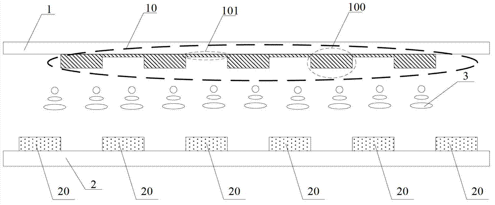
[0056] see image 3 , which is a schematic cross-sectional view of an in-cell touch screen provided by an embodiment of the present invention, the in-cell touch screen includes:

[0057] The first substrate 1 and the second substrate 2 are filled with the liquid crystal layer 3 between the first substrate 1 and the second substrate 2, and the first substrate 1 is formed with a plurality of horizontally arranged touch sensing electrodes 10 (such as image 3 The structure within the dotted line indicated by the reference numeral 10), the second substrate 2 is formed with a plurality of vertically arranged touch drive electrodes 20;

[0058] Such as Figure 4 ,for image 3 The schematic top view of the touch driving electrodes 20 and the touch sensing electrodes 10 is shown. Each touch driving electrode 20 is a strip electrode, and each touch sensing electrode 10 is composed of a plurality of touch sensing sub-electrodes 100 (such as Figure 4 The structure within the dotted ...

Embodiment 2

[0081] The in-cell touch screen provided by the embodiment of the present invention may also be: the touch driving electrodes are formed on the first substrate, and the touch sensing electrodes are formed on the second substrate;

[0082] Each touch driving electrode includes a plurality of electrically connected touch driving sub-electrodes, and each touch sensing electrode is a strip electrode;

[0083] The in-cell touch screen further includes a plurality of common electrodes formed on the second substrate along the second direction and arranged on the same layer as the touch-sensing electrodes. The common electrodes are located on any adjacent two touch-sensing electrodes. Between the electrodes, that is, the common electrodes and the touch driving electrodes are all strip electrodes and are arranged at intervals; a constant voltage is applied to the common electrodes and the touch sensing electrodes during the image display phase and the touch phase;

[0084] Wherein, a s...

Embodiment 3

[0091] In this embodiment, the touch driving electrodes (or touch sensing electrodes) and the common electrodes are arranged on different layers.

[0092] see Figure 8 , the touch driving electrode 20 is composed of a plurality of touch driving sub-electrodes 200 , and the touch sensing electrode 10 is composed of a plurality of touch sensing sub-electrodes 100 , the touch driving sub-electrodes 200 are connected by wires 201 , and the touch sensing sub-electrodes 100 are connected by wires 101 . The area where the projections of the touch drive electrodes 20 and the touch sensing electrodes 10 overlap in the vertical direction is the area where the projections of the wires 201 and the wires 101 overlap in the vertical direction. very small.

[0093] Figure 8 In the shown in-cell touch screen, the common electrodes are arranged on different layers from the touch driving electrodes 20 and the touch sensing electrodes 10 . The configuration and pattern of the common electro...


PUM

PropertyMeasurementUnit
Widthaaaaaaaaaa

Abstract

The invention discloses an embedded touch screen and a display device and aims at reducing mutual capacitance of a vertical overlapped surface of touch sensing electrodes and touch driving electrodes which are both arranged in the embedded touch screen and improving the touch control effect of the embedded touch screen. The embedded touch screen comprises a plurality of touch sensing electrodes arranged in a first direction and a plurality of touch driving electrodes arranged in a second direction perpendicular to the first direction. Each touch sensing electrode comprises a plurality of touch sensing sub electrodes which are electrically connected, and projections of the touch sensing sub electrodes in the vertical direction and projections of the touch driving electrodes in the vertical direction have no overlapped areas; and/or each touch driving electrode comprises a plurality of touch driving sub electrodes which are electrically connected, and projections of the touch driving sub electrodes in the vertical direction and projections of the touch sensing electrodes in the vertical direction have no overlapped areas.

Description

technical field [0001] The invention relates to the technical field of touch display, in particular to an embedded touch screen and a display device. Background technique [0002] The in-cell touch panel (In cell Touch Panel) is a device that integrates a touch screen and a display screen. The touch driving electrodes and the touch sensing electrodes are integrated in the display screen to realize the functions of touch control and image display at the same time. Due to the characteristics of simple structure, lightness, thinness, and low cost, the embedded touch screen has gradually become the mainstream in the display field. [0003] see figure 1 , for the touch driving electrodes 800 arranged horizontally and the touch sensing electrodes 900 arranged vertically, the coupling between adjacent touch driving electrodes 800 and touch sensing electrodes 900 generates a mutual capacitance C m (mutual capacitance), when a finger touches the screen, the touch of the finger wil...

Claims


Application Information

Patent Timeline
IPC IPC(8): G06F3/044G02F1/1333G02F1/1362
Inventor 丁小梁董学王海生刘英明任涛杨盛际赵卫杰刘红娟
Owner BEIJING BOE OPTOELECTRONCIS TECH CO LTD
Why Eureka
Try Eureka