
Reactor and manufacturing method thereof

一种电抗器、构造成的技术,应用在电感/变压器/磁铁制造、电感器、固定电感器等方向,能够解决制造设施成本及空间要求增加等问题,达到低成本的效果

Inactive Publication Date: 2016-09-21
SUMITOMO WIRING SYST LTD
View PDF9 Cites 0 Cited by
  • Summary
  • Abstract
  • Description
  • Claims
  • Application Information

AI Technical Summary

Problems solved by technology

Therefore, multiple adhesive fixing jigs and heat hardening baths must be prepared for mass production, with a corresponding increase in cost and space requirements in the manufacturing facility

Method used


Image

  • Reactor and manufacturing method thereof
  • Reactor and manufacturing method thereof
  • Reactor and manufacturing method thereof

Examples


Embodiment Construction

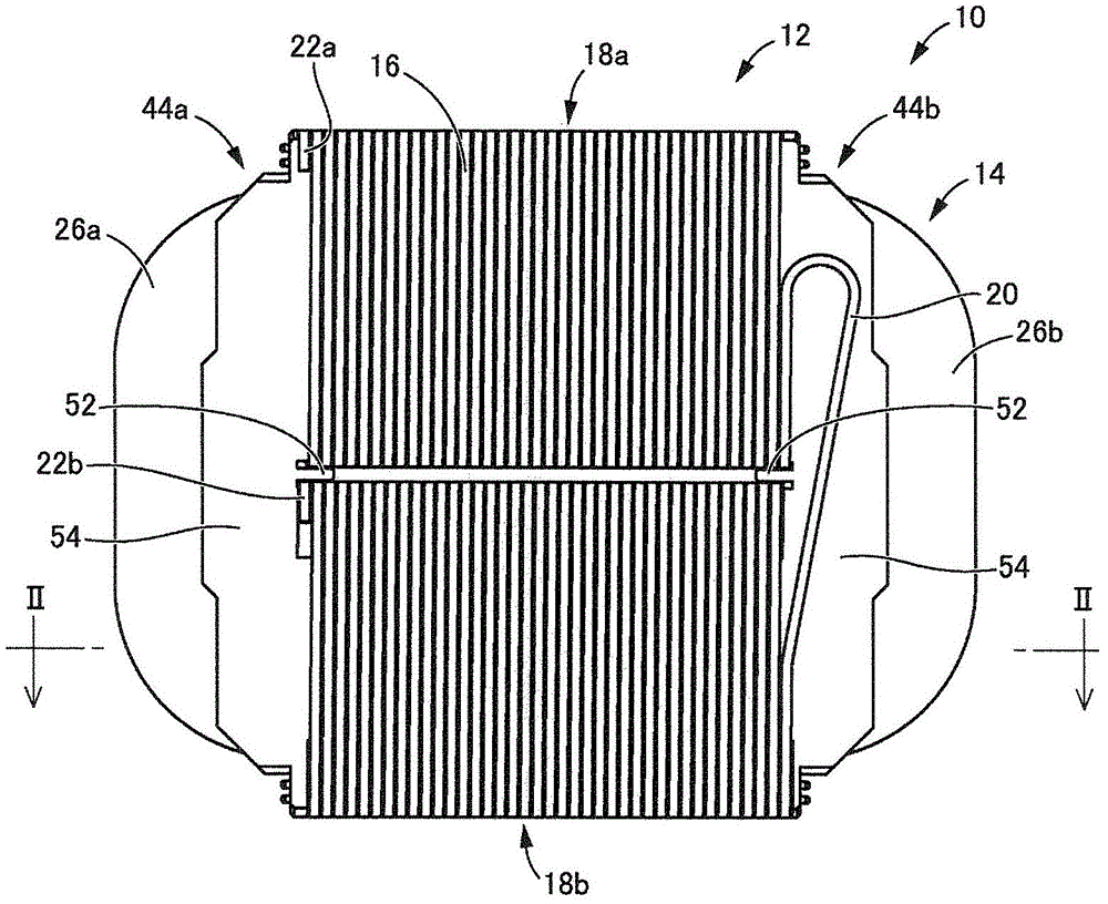
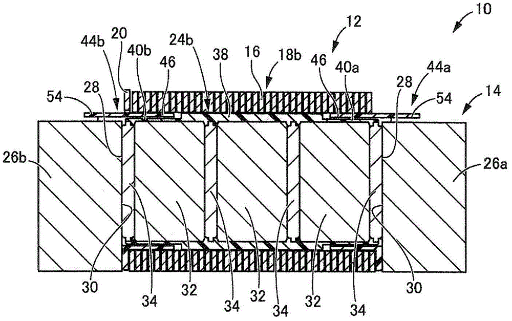
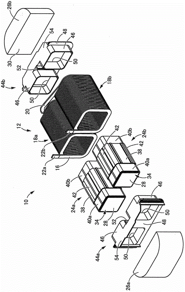
[0035] Figures 1 to 3 A reactor 10 of a first embodiment of the present invention is shown. The reactor 10 includes a coil 12 and an annular core 14 on which the coil 12 is wound. In the following description, the installation side ( figure 2 The lower side in ) is defined as the bottom, and its opposite side is defined as the top.

[0036]The coil 12 includes: a pair of coil elements 18a, 18b formed by winding a continuous winding wire 16 without any joining portion in a spiral shape; and a coil coupling portion 20, The coil coupling part 20 couples the coil elements 18a, 18b. The coil elements 18a, 18b have the same number of turns, and they have a substantially rectangular shape when viewed in the axial direction. The coil elements 18 a , 18 b are arranged side by side so that their axes are parallel to each other, and a portion of the winding wire 16 on one end of the coil 12 is bent into a U shape to form the coil coupling portion 20 . In this configuration, the wi...


PUM


Abstract

The present invention relates to a reactor and its manufacturing method. The annular iron core (14) of the reactor (10) has two iron core forming members (24a, 24b), and the iron core forming members (24a, 24b) are formed by The core segments (32) and gap plates (34) are bonded to each other with a cyanoacrylate-based adhesive (36) and the bonded core segments (32) and gaps are bonded together with a thermoplastic resin (38) The plate (34) is integrally formed by insert molding.

Description

technical field [0001] The present invention relates to a reactor used as a component of a power converter such as a DC-DC converter mounted on a hybrid vehicle. Background technique [0002] In recent years, due to increased awareness of environmental issues, hybrid or electric vehicles employing an electric motor as a power source in addition to or instead of an engine have become increasingly common. These vehicles include a reactor for stepping up the voltage from a DC power source to a driving voltage for the electric motor. [0003] For example, as described in JP-A-2008-263062 or JP-A-2010-245457, a reactor has a coil wound around an annular core. The reactor includes a switching circuit that takes out a high voltage using counter electromotive force by repeatedly turning on-off the power supply to the coil. [0004] The annular core has a plurality of core segments formed of a magnetic material, and a non-magnetic gap plate is interposed between the core segments t...

Claims


Application Information

Patent Timeline
Patent Type & Authority Patents(China)
IPC IPC(8): H01F17/06H01F27/24H01F41/02H01F27/30H01F41/00
CPCH01F17/06H01F27/263H01F27/306H01F27/325H01F2017/048Y10T29/4902
Inventor 俵秀男薮谷博美鬼塚孝浩大石明典
Owner SUMITOMO WIRING SYST LTD
Learn More