Battery assembly device

A combined device and battery technology, applied in battery pack components, circuits, electrical components, etc., can solve the problems of thermal expansion, damage of battery cells, and difficulty in dissipating heat from battery cells.

Inactive Publication Date: 2013-04-17
LITE ON TECH CHANG ZHOU CO LTD +1
View PDF3 Cites 2 Cited by
  • Summary
  • Abstract
  • Description
  • Claims
  • Application Information

AI Technical Summary

Problems solved by technology

However, the battery unit will also generate heat due to the supply of current. The heat generated by the battery unit is not easy to dissipate, which will easily cause the battery unit to generate high temperature and vaporize the internal electrolyte or electrode material.
In this way, the battery cell may

Method used


Image

  • Battery assembly device
  • Battery assembly device
  • Battery assembly device

Examples


Embodiment Construction

[0062] In order to make the above and other objects, features and advantages of the present invention more comprehensible, specific embodiments of the present invention are listed below and described in detail in conjunction with the accompanying drawings.

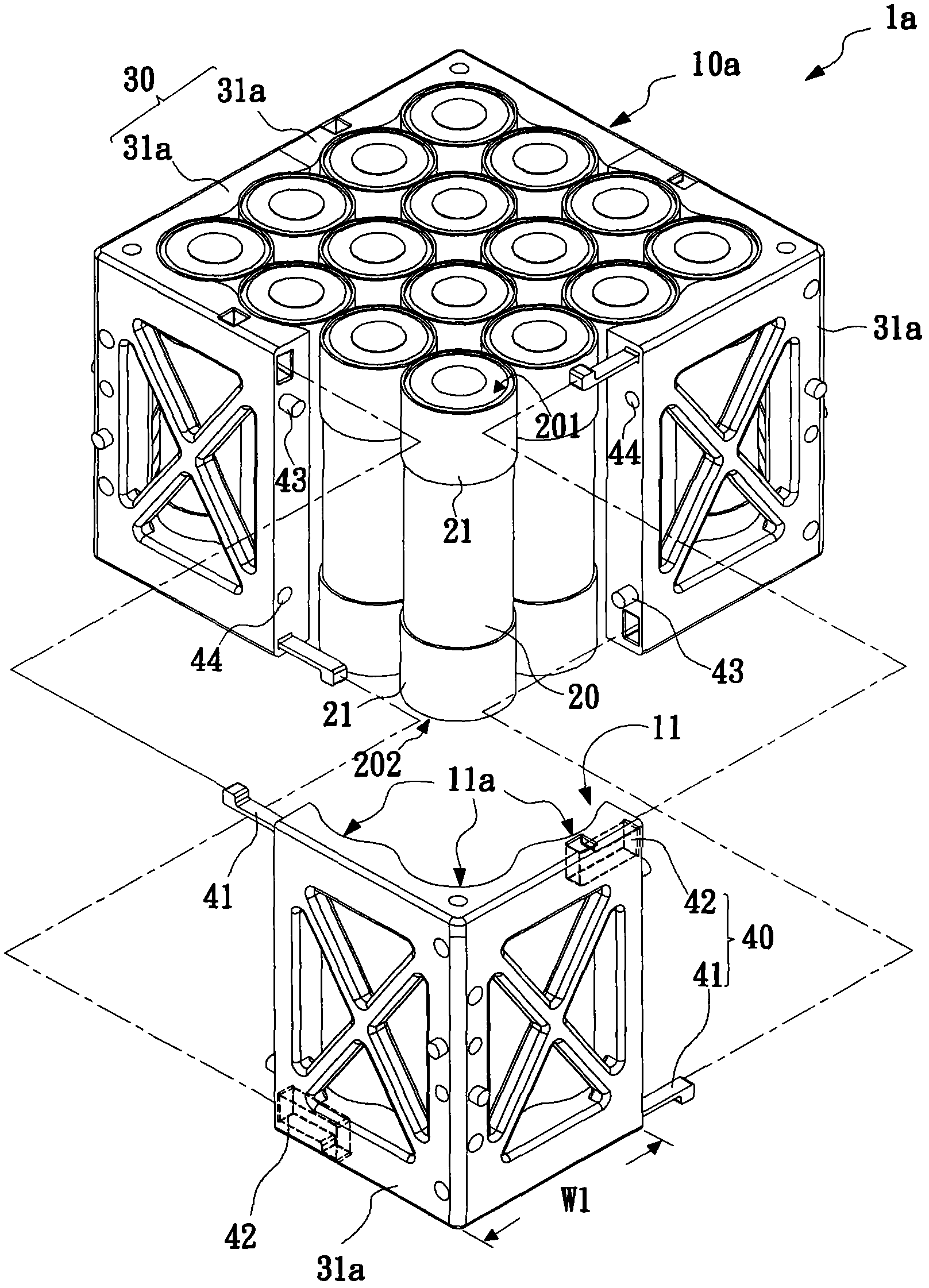
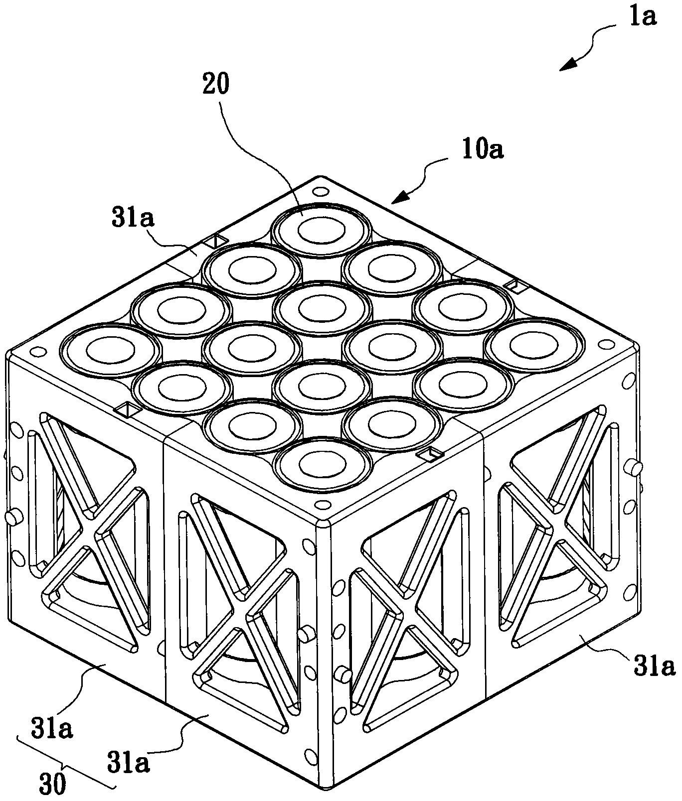
[0063] Please refer to the following Figure 1 ~ Figure 2 Relevant schematic diagrams of the first embodiment of the battery assembly device of the present invention, wherein figure 1 An exploded view of the first embodiment of the battery assembly device of the present invention, figure 2 A perspective view of the first embodiment of the battery assembly device of the present invention.

[0064] In the first embodiment of the present invention, the battery assembly device 1a includes a first frame body 10a and a plurality of battery units 20, and the plurality of battery cells 20 are disposed in the first frame body 10a. The appearance of the battery unit 20 may be cylindrical, but the present invention does not limit ...


PUM


Abstract

The invention provides a battery assembly device, comprising a first framework and a plurality of battery units. The first framework possesses inner wall surfaces. The plurality of battery units are arranged in the first framework, wherein any battery unit possesses at least one non-stop sheet and is in contact with another non-stop sheet of another battery unit through the non-stop sheet or is in contact with inner wall surfaces of the first framework through the non-stop sheet.

Description

technical field [0001] The invention relates to a battery assembly device, in particular to a battery assembly device capable of preventing battery units from sliding randomly. Background technique [0002] Today's battery packs are structurally fixed battery holders for accommodating multiple battery cells. However, because the structure of the battery pack is fixed, the number of battery cells that can be accommodated is also fixed. If the number of battery cells is to be increased, the structure of the battery pack must be redesigned, which will be limited in use. On the other hand, in the prior art, the battery cells are in direct and close contact with each other to avoid the battery cells from slipping. However, the battery cell will also generate heat due to the supply of current, and the heat generated by the battery cell is not easy to dissipate, which may easily cause the battery cell to generate high temperature and vaporize the internal electrolyte or electrode ...

Claims


Application Information

Patent Timeline
IPC IPC(8): H01M2/10
CPCY02E60/10
Inventor 卢成基蔡玟骏欧薰雯
Owner LITE ON TECH CHANG ZHOU CO LTD
Why Eureka
Try Eureka