Microwave anechoic chamber performance measuring method

A microwave anechoic chamber and measurement method technology, which is applied in the direction of measuring devices, measuring electrical variables, transmission monitoring, etc., can solve the problems of unguaranteed measurement repeatability and accuracy, long time-consuming, heavy workload, etc., to improve operational stability and The effect of measurement accuracy, improvement of measurement efficiency, and reduction of measurement error

Active Publication Date: 2013-04-17
CHINA SHIP DEV & DESIGN CENT
View PDF1 Cites 26 Cited by
  • Summary
  • Abstract
  • Description
  • Claims
  • Application Information

AI Technical Summary

Problems solved by technology

[0003] Usually the darkroom measurement is done manually, and the control of each part is also done manually. Not only is the workload heavy, it takes a long time, and the measurement repeatability and accuracy cannot be guaranteed.

Method used


Image

  • Microwave anechoic chamber performance measuring method
  • Microwave anechoic chamber performance measuring method
  • Microwave anechoic chamber performance measuring method

Examples


Embodiment Construction

[0020] The present invention will be further described below in conjunction with the embodiments and accompanying drawings.

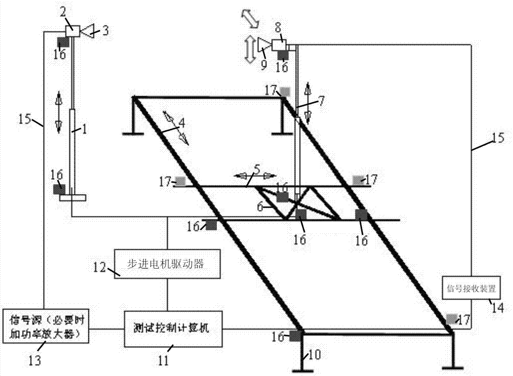
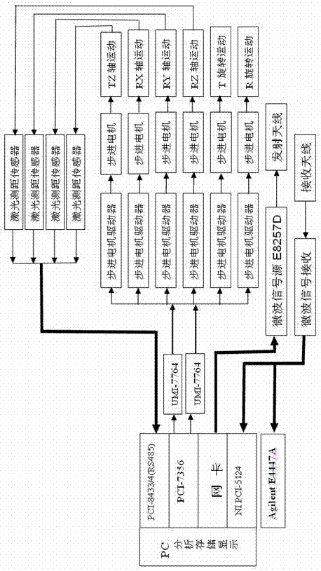
[0021] The microwave anechoic chamber performance measurement system includes test bench and control equipment, figure 1 It is a structural schematic diagram of an embodiment of the present invention, figure 2 It is a control block diagram of an embodiment of the present invention.

[0022] The test bench (in this embodiment, the test bench is made of MC nylon material) includes a transmitting antenna stand for lifting and rotating the transmitting antenna, and a receiving antenna stand for moving and rotating the receiving antenna in three-dimensional space; The transmitting antenna stand is located in the transmitting area of ​​the microwave anechoic chamber, and the receiving antenna stand is located in the quiet zone of the microwave anechoic chamber.

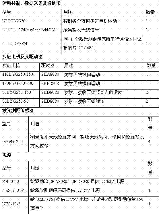
[0023] The control equipment includes a processor 11 (a computer in this embodiment), a laser ...


PUM


Abstract

The invention provides a microwave anechoic chamber performance measuring method, which comprises the following steps of: adopting a microwave anechoic chamber performance measuring system, and setting a dead zone parameter, a measuring frequency, a signal source power, a scanning trace and a kinematic velocity of a receiving antenna, and a rotation direction and a rotation velocity of a transceiving antenna according to the requirements of a microwave anechoic chamber performance analysis test; driving a signal source according to the signal source power; driving each stepping motor to control each moving part to move according to the scanning trace and the kinematic velocity of the receiving antenna, and the rotation direction and the rotation velocity of the transceiving antenna; and controlling a signal receiver to receive a signal of the receiving antenna according to the measuring frequency, and storing the signal. The method can be adopted to be applied in a microwave anechoic chamber flexibly so as to measure along different scanning traces; and a computer is adopted to realize automatic measurement of microwave anechoic chamber dead zone reflectivity level, cross polarization character, multi-path loss uniformity, and field uniformity performance indexes, so that the measuring efficiency is improved.

Description

technical field [0001] The invention belongs to the field of electromagnetic compatibility, and in particular relates to a method for measuring the performance of a microwave anechoic chamber. Background technique [0002] The microwave anechoic chamber is an important test facility for microwave antenna measurement, RCS measurement, and electromagnetic compatibility measurement. Performance indicators such as reflectivity level and field uniformity in the quiet zone of the microwave anechoic chamber have a significant impact on the test measurement in the microwave anechoic chamber. Therefore, the performance index of the quiet zone needs to be measured for the acceptance of the darkroom after it is built or for the regular inspection during use. Usually the microwave anechoic chamber performance measurement system mainly includes microwave signal transmitting part, microwave signal receiving part, motion scanning part, data acquisition and analysis part, etc. The perform...

Claims


Application Information

Patent Timeline
Patent Type & Authority Applications(China)
IPC IPC(8): H04B17/00G01R35/00
Inventor 郑生全蒋炎坤黄松高汪巅朱传焕温定娥
Owner CHINA SHIP DEV & DESIGN CENT
Why Eureka
Try Eureka