

Rope braking apparatus
一种制动装置、绳索的技术,应用在卷扬装置、安全装置、制动器类型等方向,能够解决流体泄漏制动力、污染、下降环境等问题,达到解决制动力下降的效果
- Summary
- Abstract
- Description
- Claims
- Application Information
AI Technical Summary
Problems solved by technology
Method used
Image

Examples
Embodiment Construction
[0028] Hereinafter, embodiments of the present invention will be described in detail with reference to the accompanying drawings so that those skilled in the art to which the present invention pertains can easily implement. However, the present invention can be implemented in various forms and is not limited to the embodiments described here. Like parts are given the same reference numerals throughout the specification.
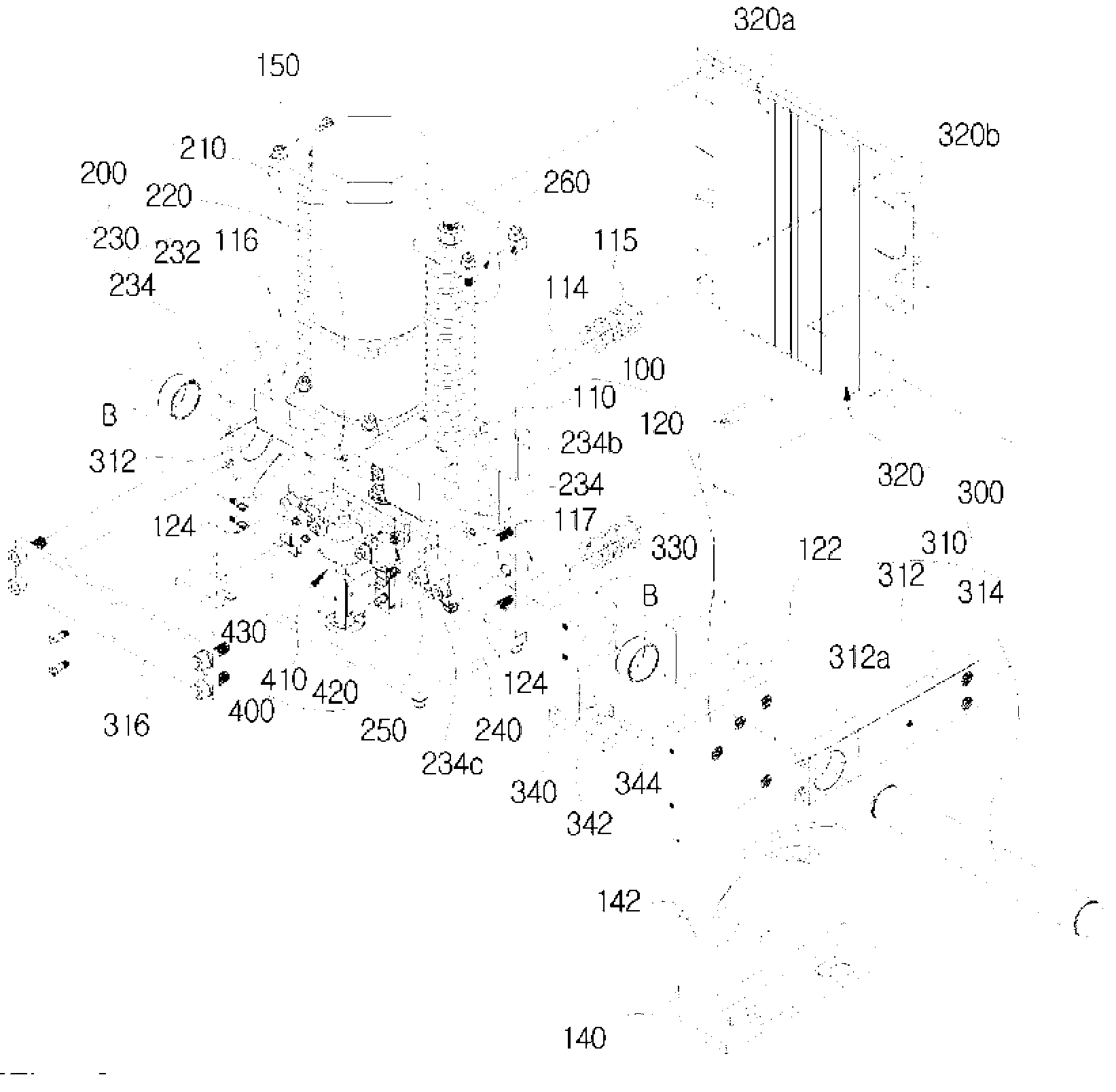
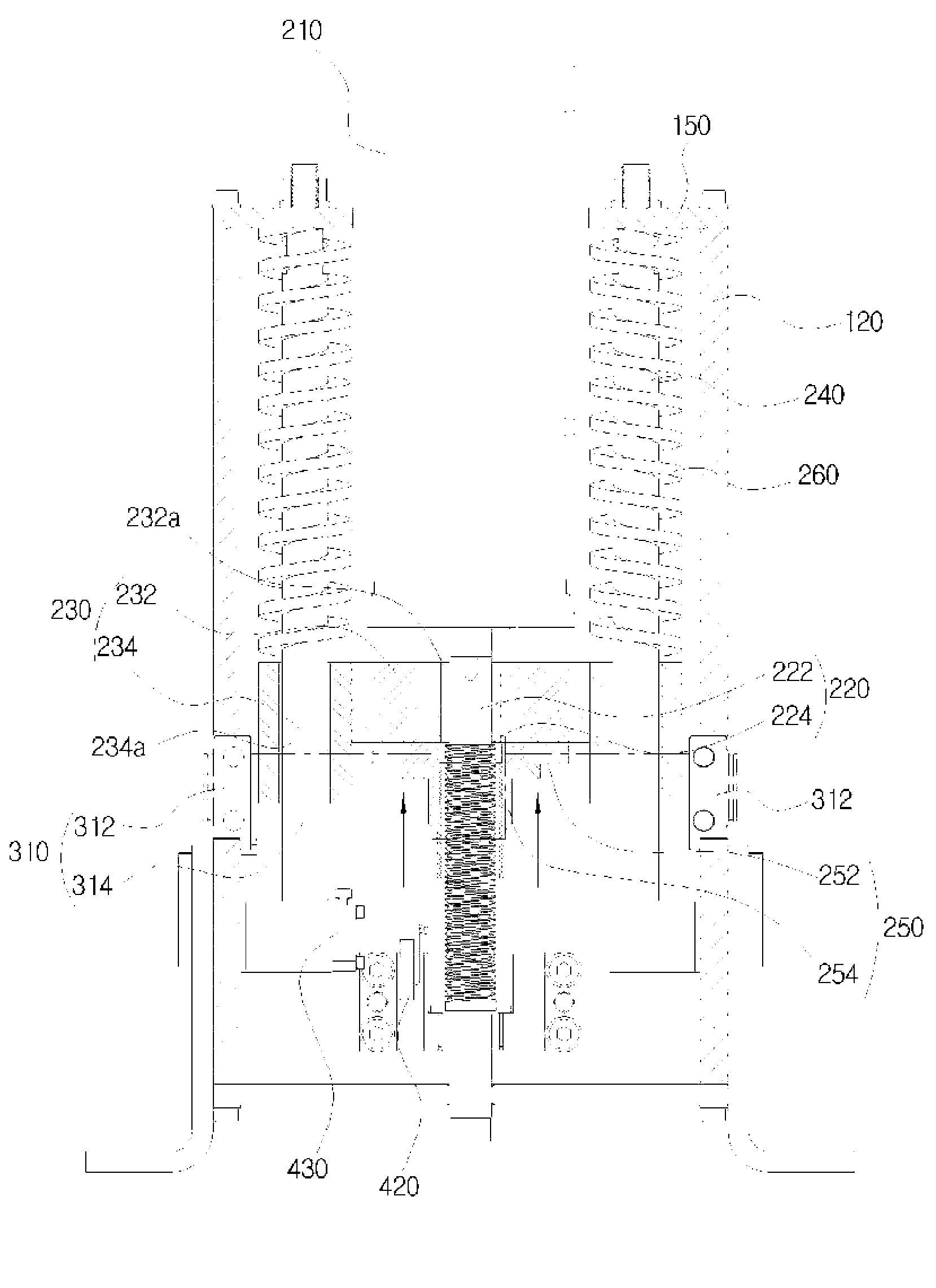
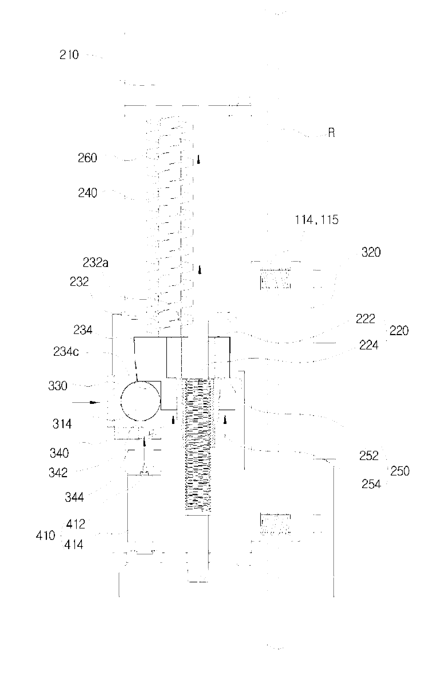
[0029] Such as Figure 1 to Figure 7 As shown, the rope braking device of the present invention generally includes an installation body 100 , a driving unit 200 , a pressurizing part 300 and a movement control part 400 .
[0030] First of all, the installation body 100 functions as the overall cabinet of the present invention, and is formed in the form of a square box as a whole, specifically with a structure in which an installation space 130 is formed inside by arranging side panels 120 on both sides of the back panel 110 .
[0031] In addition, the side ...
PUM
 Abstract
Description
Claims
Application Information