Systems and methods of wireless power transfer with interference detection

A technology of power and power loss, applied in transmission systems, near-field transmission systems, electromagnetic wave systems, etc., can solve problems such as short-range wireless transmission

Active Publication Date: 2013-04-17
TEXAS INSTR INC
View PDF7 Cites 14 Cited by
  • Summary
  • Abstract
  • Description
  • Claims
  • Application Information

AI Technical Summary

Problems solved by technology

The main disadvantage of this basic form o

Method used


Image

  • Systems and methods of wireless power transfer with interference detection
  • Systems and methods of wireless power transfer with interference detection
  • Systems and methods of wireless power transfer with interference detection

Examples


Embodiment Construction

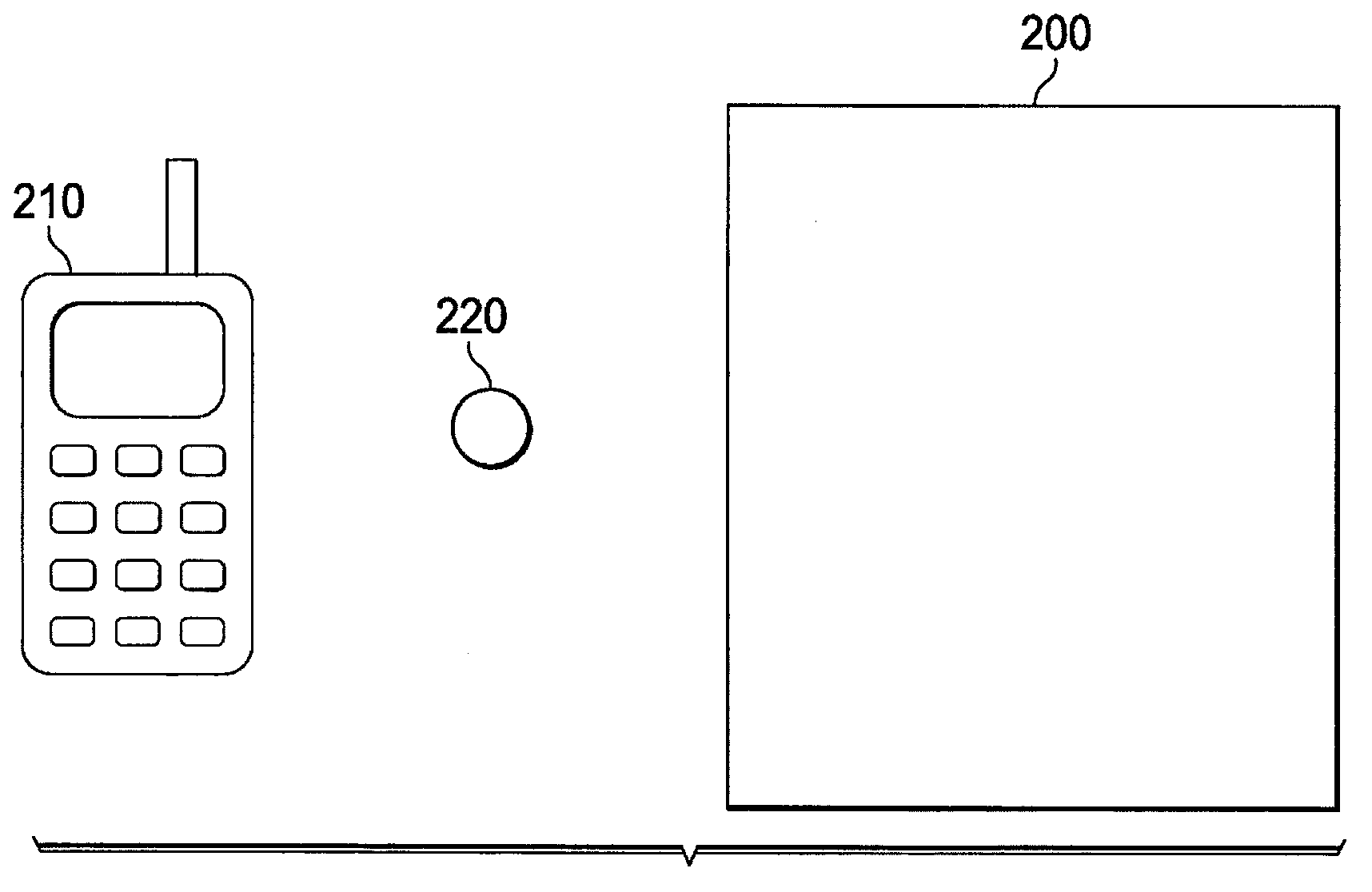
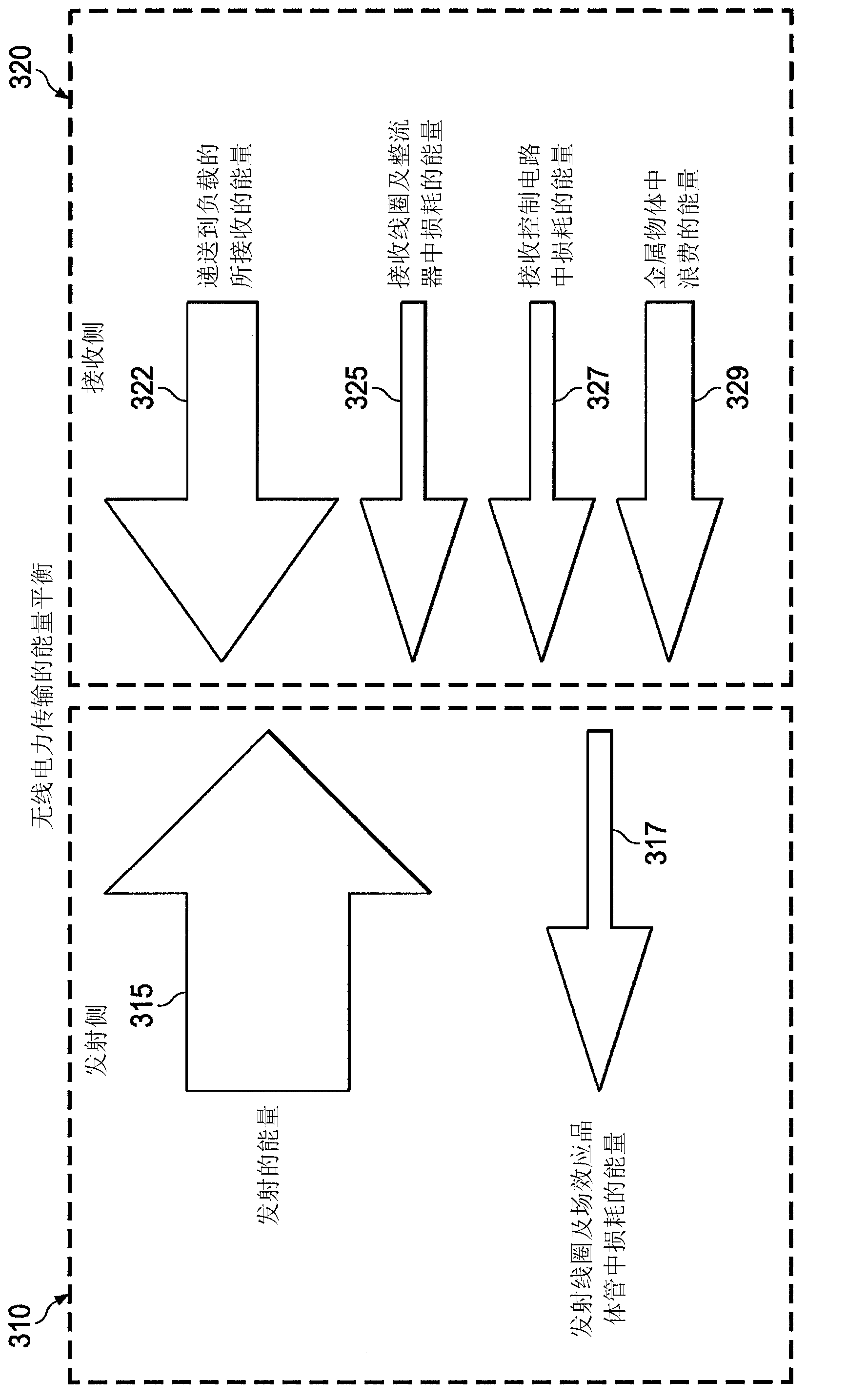
[0020] With wireless charging, the receiving part of the system can periodically communicate to the primary side eg its operating voltage, current and power levels and required corrective actions from the primary side to keep the secondary power parameters within the desired operating range. The performance of this system can be significantly degraded when parasitic metallic objects are accidentally or intentionally placed in close proximity to the transmit coil. Some of the emitted energy can be coupled by these metallic objects and wasted as heat. Not only does this degrade the performance of the system, but it also creates the risk that metallic objects such as coils and keys become hot enough to cause a fire, cause plastic parts to deform, or burn the operator's skin when touched.

[0021] The systems and methods disclosed herein for wireless power transfer systems with jamming detection detect parasitic metal objects associated with placed in close proximity to system coi...


PUM


Abstract

Systems and methods of wireless power transfer system with interference detection are disclosed which detect possible excessive energy transfer associated with parasitic metal objects placed in close proximity with system coils. Power received on the receiving side of the system is compared with power consumed on the primary side (610-640). If power consumed on the primary side substantially exceeds power received on the secondary side, power transfer is discontinued (650, 660). If not, power transfer is continued (650, 670).

Description

technical field [0001] The present invention relates to power electronics and, more particularly, to wireless power transfer. Background technique [0002] Wireless energy transfer or wireless power is the transmission of electrical energy from a source to an electrical load without interconnecting wires. Wireless transmission is useful in situations where interconnect lines are inconvenient, dangerous, or impossible. Wireless power differs from wireless communication in that the signal-to-noise ratio (SNR), or the percentage of received energy, becomes critical only when the signal is too low to adequately recover. For wireless power transmission, efficiency is a more important parameter. [0003] Two common forms of coupling in wireless power transmission are inductive coupling and resonant inductive coupling. Wireless power transfer systems typically consist of electromagnetically coupled transmit and receive coils. Due to coil coupling, energy from the primary side c...

Claims


Application Information

Patent Timeline
IPC IPC(8): H02J17/00
CPCH04B5/0043H04B5/0093H04B5/0075H04B5/0037H02J50/12H02J50/70H02J50/60
Inventor 弗拉迪米尔·A·穆拉托夫埃里克·G·奥廷格
Owner TEXAS INSTR INC
Why Eureka
Try Eureka