

Fence and installation method thereof
A technology for fences and mounting holes, which is applied in the direction of fences, building types, buildings, etc., can solve the problems of time-consuming and laborious installation and disassembly, low recycling rate, damaged parts, etc., and achieve high safety, high recycling rate, and installation method simple effect
- Summary
- Abstract
- Description
- Claims
- Application Information
AI Technical Summary
Problems solved by technology
Method used
Image

Examples
Embodiment 1
[0042] Such as Figure 8 As shown, 1) Insert two uprights 1 into the ground according to the width of the mesh 5, and the height exposed on the ground is the same as the height of the mesh 5;
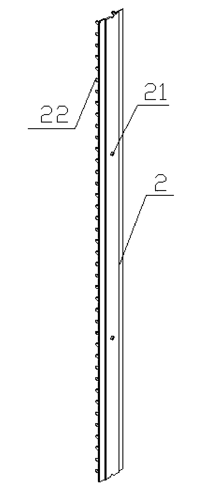
[0043] 2) Disassemble the pressure plate 2 exposed on the ground from the column 1, and keep the pressure plate 2 inserted into the ground;
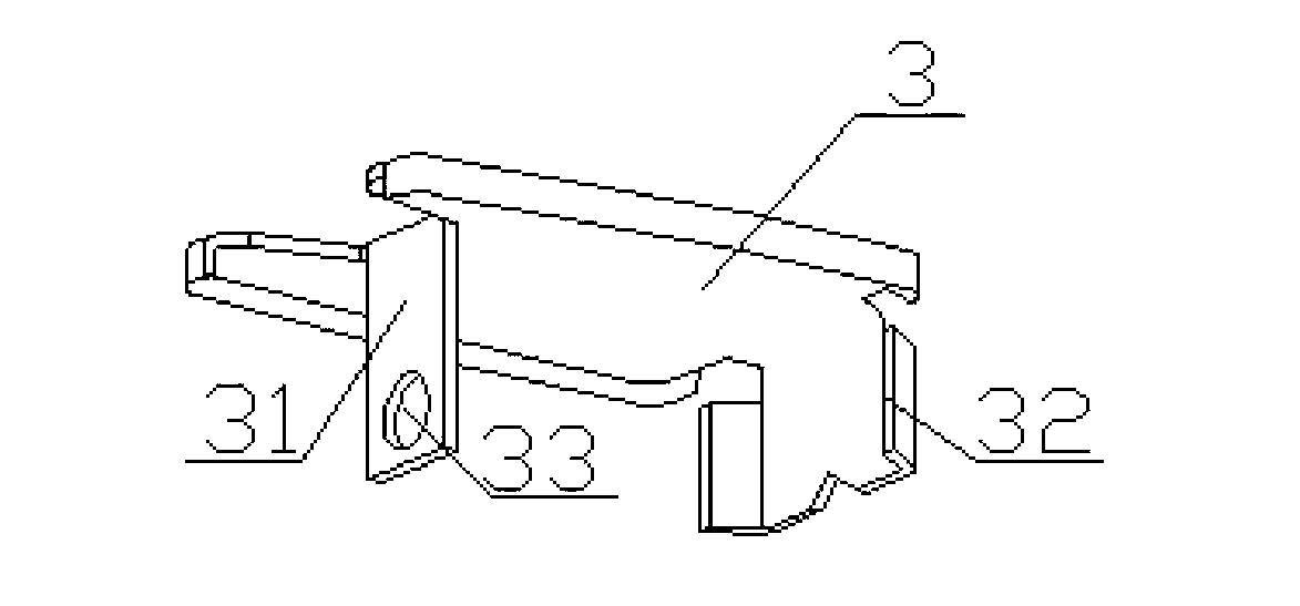
[0044] 3) Install the top cover 3 on the top of the column 1;
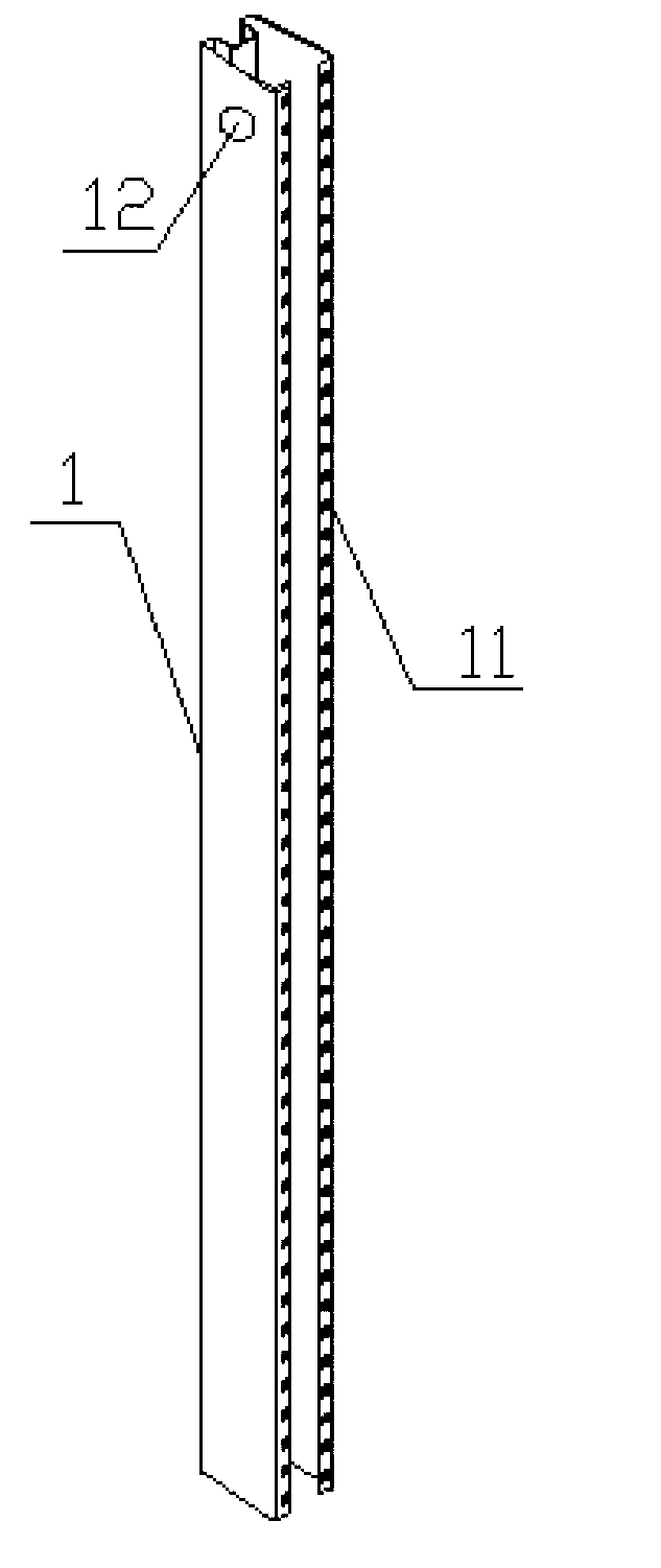
[0045] 4) Install the crossbar connector 7 on the left column surface and the right column surface above the column 1 through the bolt one 9 through the fixing hole three 71 and the installation hole 12;
[0046] 5) Install the cross bar 6 between the cross bar connectors 7, and pass the bolt 8 through the fixing hole 4 72 and the fixing hole 2 61 to fix it;
[0047] 6) Paste the mesh 5 between the two columns 1, pass the bolt 8 through the mesh 5 and the second bolt hole 62, and fix the mesh 5 on the cross bar 6;
[0048] 7) Insert the pinion 22 of the pressure plate 2 into the in...
Embodiment 2
[0050] 1) Insert the two columns 1 into the ground according to the width of the mesh 5, and the height exposed on the ground is the same as the height of the mesh 5;
[0051] 2) Disassemble the pressure plate 2 exposed on the ground from the column 1, and keep the pressure plate 2 inserted into the ground;
[0052] 3) Install the crank arm 4 on the top of the column 1;
[0053] 4) Install the crossbar connector 7 on the left column surface and the right column surface above the column 1 through the bolt one 9 through the fixing hole three 71 and the installation hole 12;
[0054] 5) Install the cross bar 6 between the cross bar connectors 7, and pass the bolt 8 through the fixing hole 4 72 and the fixing hole 2 61 to fix it;
[0055] 6) Paste the mesh 5 between the two columns 1, pass the bolt 8 through the mesh 5 and the second bolt hole 62, and fix the mesh 5 on the cross bar 6;
[0056] 7) Insert the pinion 22 of the pressure plate 2 into the insertion hole 11 through th...
PUM
 Abstract
Description
Claims
Application Information