Air intake device for internal combustion engine

A technology of air intake device and internal combustion engine, which is applied in the direction of fuel air intake, combustion air/combustion-air treatment, charging system, etc., which can solve the problems that the intake noise cannot be sufficiently reduced, and achieve the goal of reducing the intake noise Effect

Active Publication Date: 2013-04-24
HONDA MOTOR CO LTD
View PDF6 Cites 5 Cited by
  • Summary
  • Abstract
  • Description
  • Claims
  • Application Information

AI Technical Summary

Problems solved by technology

[0005] However, the air intake device of the internal combustion engine described in the above-mentioned Patent Document 1 may not be effective because the area sandwiched between the inner peripheral surface of the intake passage and the outer peripheral surface of the cylinder or part of the cylinder is open in the circumferential direction. Fully surround the high-speed air flow to fully suppress the generation of vortices, so that the intake noise cannot be sufficiently reduced

Method used


Image

  • Air intake device for internal combustion engine
  • Air intake device for internal combustion engine
  • Air intake device for internal combustion engine

Examples


no. 1 approach

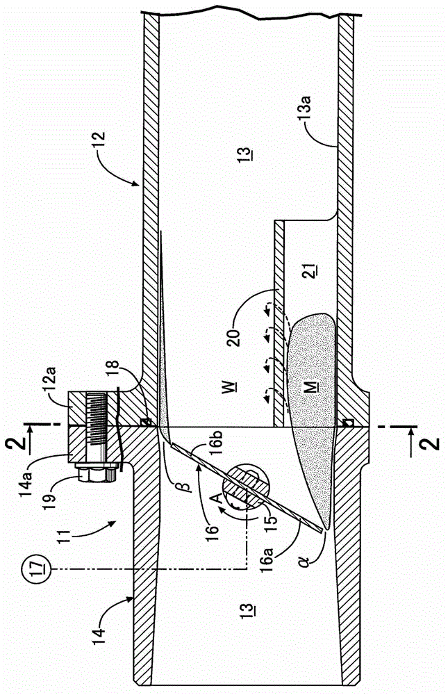
[0030] An intake device for supplying intake air to a combustion chamber of an internal combustion engine includes a throttle valve 11 on the upstream side and an intake pipe 12 on the downstream side. An air cleaner (not shown) is connected upstream of the throttle valve 11 , and a cylinder head (not shown) is connected downstream of the intake pipe 12 . An intake passage 13 through which intake air flows is formed inside the throttle valve 11 and the intake pipe 12 .

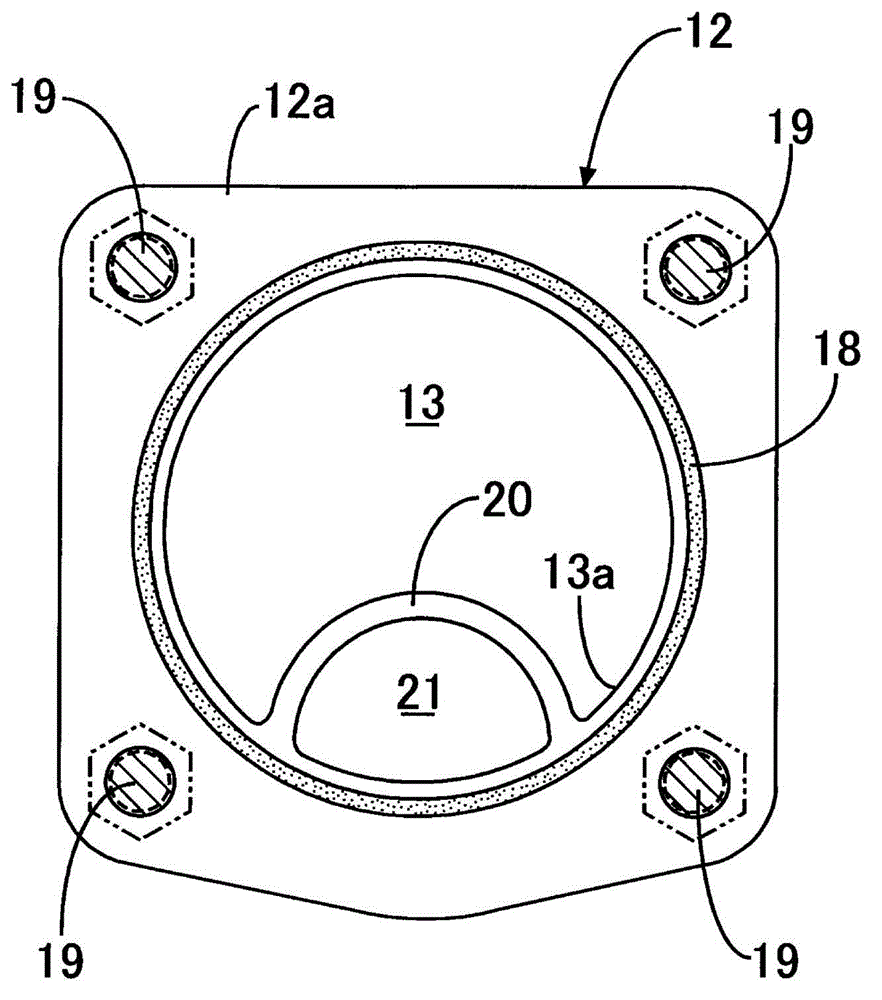
[0031] Throttle valve 11 has: throttle valve body 14, and it is penetrated for the intake passage 13 of circular section; Valve rod 15, it is set to intersect with intake passage 13; And disc-shaped spool 16, it is fixed on valve The rod 15 is driven by an electric actuator 17 to rotate within a predetermined angle range. The throttle body 14 and the intake pipe 12 are joined together by fastening flanges 14 a , 12 a formed at their opposite ends with bolts 19 . . . via an O-ring 18 .

[0032] When the valve...

no. 3 approach

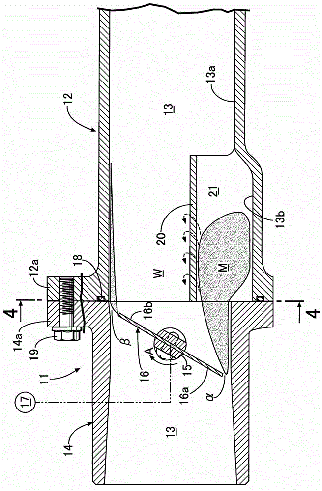
[0042] The third embodiment is a modification of the second embodiment in which the recess 13b is provided in the intake passage 13. In the second embodiment, the cross section of the first partition 20 is arc-shaped, while in the third embodiment The plate 20 is formed in a trapezoidal shape in section. In addition, the central portion of the flat second partition plate 22 arranged above the first partition plate 20 is connected to the central portion of the first partition plate 20 , and both ends of the second partition plate 22 are connected to the wall surface of the intake passage 13 . 13a connection.

[0043] As a result, since the rigidity of the first partition 20 is increased by the second partition 22, the first partition 20 is prevented from vibrating due to the air flow, and the generation of secondary intake air due to the vibration of the first partition 20 can be suppressed. noise. Moreover, two second flow paths 23, 23 with triangular cross-sections are form...


PUM


Abstract

The invention provides an air intake device for an internal combustion engine, and air intake noise produced by open of a throttle valve is effectively prevented. Through rotation of a throttle valve's valve rod disposed in an air intake path of the combustion engine, when an end of a platelike valve body moves towards an upstream side of the air intake path and the other end moves towards a downstream side of the air intake path, a main stream at high flow velocity passing through a gap between an end of the valve body and a wall of the air intake path mixes with side flows of downstream of the valve body, and form a vortex so the air intake noise is formed. However, two ends of a first partition plate is disposed approximately parallel to a flow direction of intake air and includes opposite ends connected to a first inner wall surface of the air intake path closer to the first end than the second end. The first partition plate has a substantially curved convex shape protruding radially inward of the air intake path, so the main stream is surrounded from the wall of the air intake path and the first partition plate and the main stream does not mix with the side flows, thereby restraining generation of the vortex and effectively reducing the air intake noise.

Description

technical field [0001] The present invention relates to an air intake device for an internal combustion engine, wherein the throttle valve of the internal combustion engine has a plate-shaped valve core, and the valve core is fixed to a rotatable valve stem to open and close the intake passage. One end side of the core moves toward the upstream side of the intake passage and the other end side moves toward the downstream side of the intake passage. Background technique [0002] An air intake device for an internal combustion engine is known from the following Patent Document 1, in which a cylinder or a portion is arranged approximately parallel to the flow direction of intake air in the radial central portion of the air intake passage on the downstream side of the valve element of the throttle valve. A cylinder for passing the high-speed air flow through the opening formed between the intake passage and the valve core when the throttle valve is opened, between the inner peri...

Claims


Application Information

Patent Timeline
Patent Type & Authority Applications(China)
IPC IPC(8): F02D9/02F02M35/10
CPCF02M35/10F02M35/1211F02D9/02F02D9/104
Inventor 若松健山岸仁
Owner HONDA MOTOR CO LTD
Why Eureka
Try Eureka