Air intake device

a technology of air intake and air passage, which is applied in the direction of combustion engine, combustion engine, fuel air treatment, etc., can solve the problems of difficult to reduce the sound (noise) of the intake air, and difficult to substantially cool air flowing in the air intake passage. , to achieve the effect of reducing the temperature of the intake air flowing in the air intake passage and reducing the frequency of the air intake sound having a broad frequency band

Inactive Publication Date: 2008-07-03
DENSO CORP
View PDF54 Cites 6 Cited by
  • Summary
  • Abstract
  • Description
  • Claims
  • Application Information

AI Technical Summary

Benefits of technology

[0010]Thus, the intake air flowing in the air intake passage formed by the inner pipe member is cooled by the air introduced in to the space. Moreover, the inner pipe member has the sound transmission portion which is formed at the wall portion defining the air intake passage. The sound of the intake air flowing in the air intake passage is emitted to the space from the sound transmission portion. A part of the sound emitted from the sound transmission portion is transferred to the opening end of the atmosphere intake side from the sound transmission portion, and other part of the sound is t

Problems solved by technology

In this case, it is difficult to substantially cool air flowing in the air intake passage.
Thus, it is difficult to reduce the sound of a frequency other than the determined

Method used


Image

  • Air intake device
  • Air intake device
  • Air intake device

Examples


embodiments

Exampled Embodiment

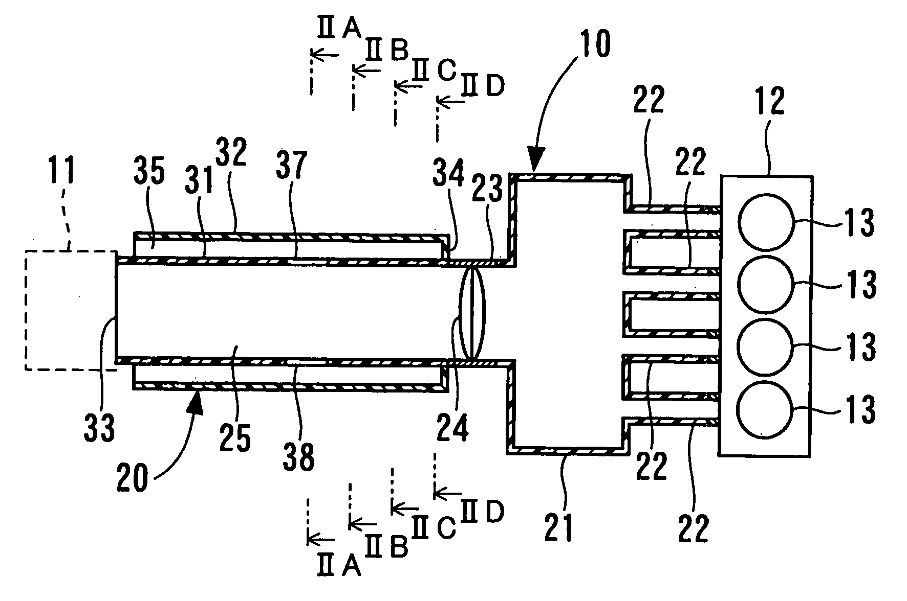
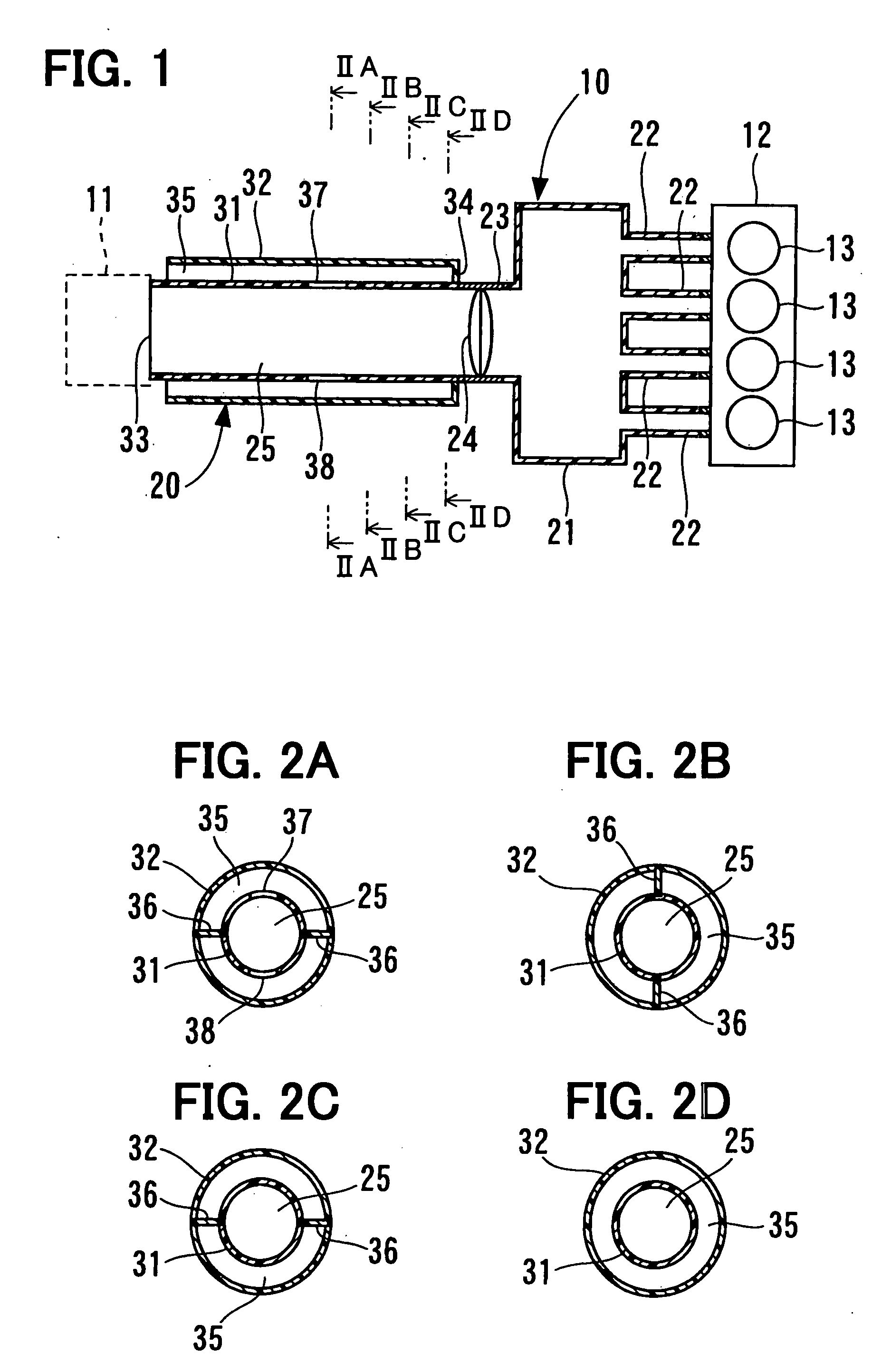
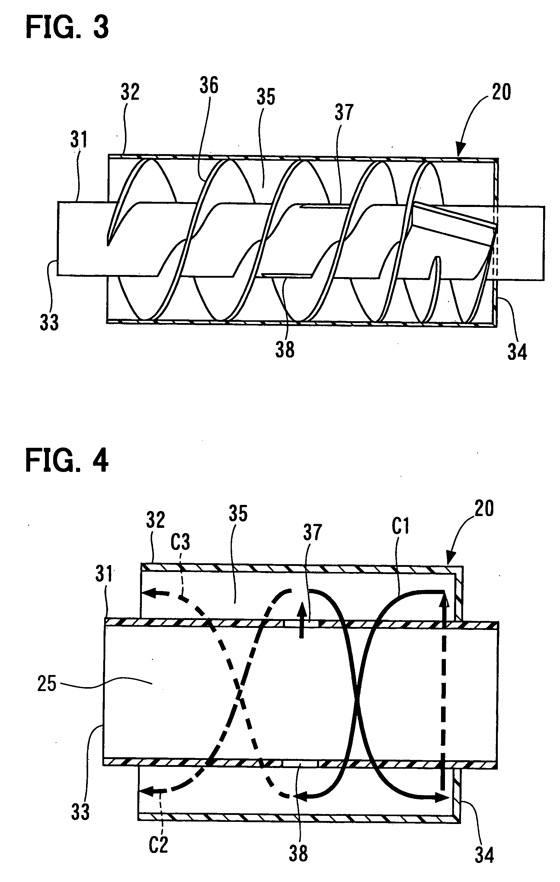
[0017]An air intake device 20 according to an exampled embodiment of the present invention will be described with reference to FIGS. 1-5. FIG. 1 shows an air intake system 10 where the air intake device 20 is suitably used.

[0018]As shown in FIG. 1, the air intake system 10 includes the air intake device 20, an air cleaner 11 and an engine 12 (for example, internal-combustion engine). The air intake device 20 has a surge tank 21 which are communicated with multiple intake manifolds 22. That is, the intake manifolds 22 are branched from the surge tank 21, and have the number corresponding to the number of the cylinders 13 of the engine 12 to be respectively connected with the cylinders 13.

[0019]The air cleaner 11 is mounted to an end of the air intake device 20, and houses therein an air cleaner element (not shown). This end is positioned at an opposite side of the air intake device 20 to the engine 12. Air sucked into the engine 12 passes through the air cleaner 11...


PUM


Abstract

An air intake device includes an inner pipe member having a substantially cylindrical shape and defining therein an air intake passage by a wall portion of the inner pipe member, and an outer pipe member which surrounds a periphery side of the inner pipe member to define therebetween a space. The air intake passage communicates a surge tank with an atmosphere intake port through which air is introduced into the surge tank. The wall portion of the inner pipe member has at least one sound transmission portion through which sound is more readily transferred than other portions of the wall portion. The space has one end which is opening and positioned at a side of the atmosphere intake port, and the other end which is closed and positioned at a side of the surge tank.

Description

CROSS REFERENCE TO RELATED APPLICATION[0001]This application is based on a Japanese Patent Application No. 2006-266692 filed on Sep. 29, 2006, the disclosure of which is incorporated herein by reference.FIELD OF THE INVENTION[0002]The present invention relates to an air intake device.BACKGROUND OF THE INVENTION[0003]Generally, it is desirable to reduce air intake noise (air intake sound) in an air intake passage in which intake air which is sucked to an internal-combustion engine flows. For example, with reference to JP-56-138108A, a side branch is arranged at the periphery side of a pipe member which forms the air intake passage, so that a resonance frequency varies corresponding to the length of the axial direction of the side branch. Thus, the noise having the natural frequency of the intake air flowing in the air intake passage is reduced.[0004]However, the efficiency for filling the intake air (sucked to internal-combustion engine) into the internal-combustion engine will becom...

Claims


Application Information

Patent Timeline
IPC IPC(8): F02M35/12F02M35/104
CPCF02B29/0456F02M35/1277F02M35/1272
Inventor HAYASHI, KAZUHIRO
Owner DENSO CORP
Why Eureka
Try Eureka