Intake noise reduction device and straddle-type vehicle including the same

a technology of noise reduction device and intake, which is applied in the direction of air cleaner and silencer combination, combustion-air/fuel-air treatment, cycle equipment, etc., can solve the problems of limited design and difficulty in ensuring the necessary capacity of the resonator, and achieve the reduction of the intake performance of the engine, the effect of reducing the noise, and preventing the layout and design of the surroundings

Active Publication Date: 2015-12-03
YAMAHA MOTOR CO LTD
View PDF4 Cites 5 Cited by
  • Summary
  • Abstract
  • Description
  • Claims
  • Application Information

AI Technical Summary

Benefits of technology

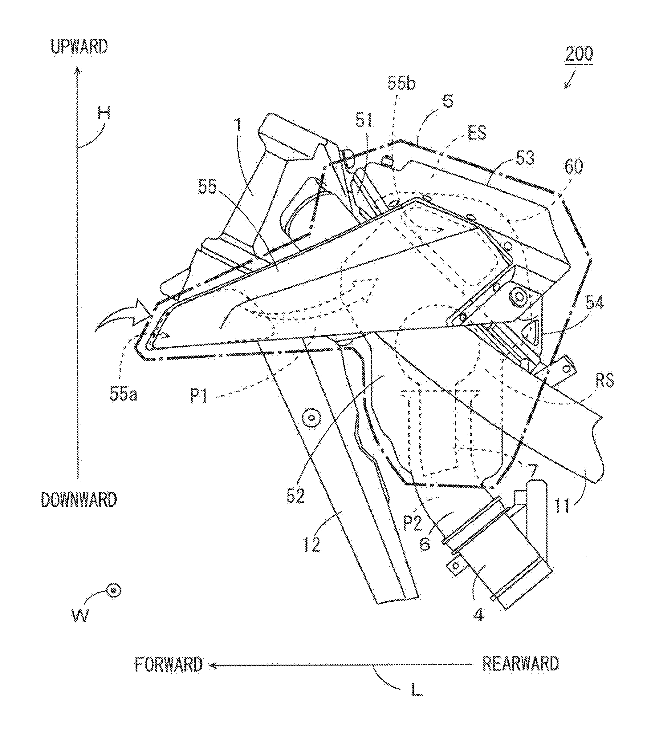
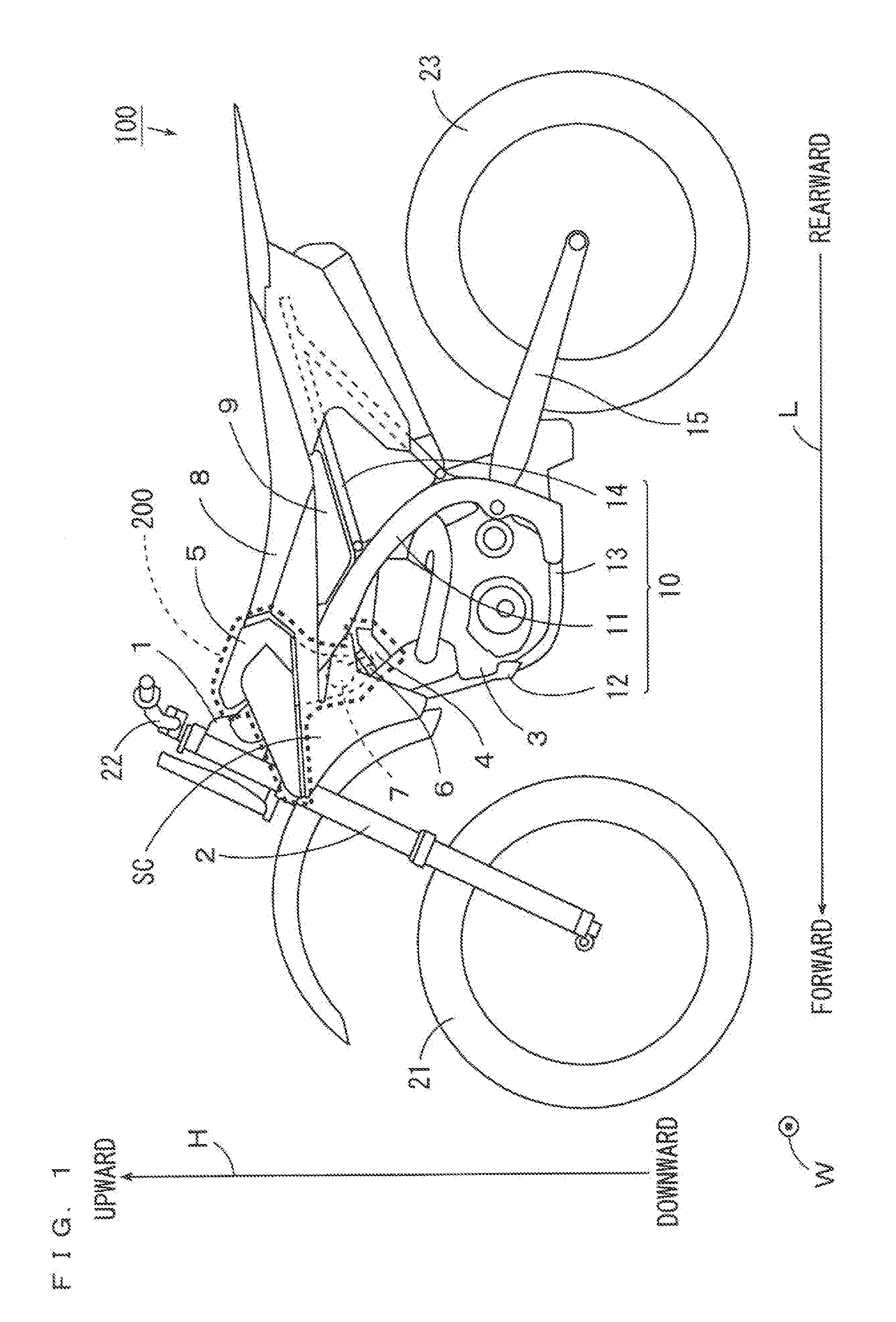
[0009]In the intake noise reduction device, the opening end of the pipe portion of the resonator is inserted into the intake funnel, so that the opening end of the pipe portion of the resonator is close to an intake valve positioned downstream of the intake passage. Thus, noise reduction is improved. Further, the resonator is arranged in the air cleaner, so that limitation of the layout and design of the surroundings of the intake funnel due to the presence of the resonator is prevented.
[0010]In this case, the cross sectional area of the passage formed between the inner peripheral surface of the intake funnel and the outer peripheral surface of the pipe portion is set to not less than the opening area of the intake passage of the throttle body opened to the maximum throttle opening, whereby the intake amount in the intake passage of the throttle body is not limited by the pipe portion of the resonator inserted into the intake funnel. Therefore, a reduction in intake performance of the engine is prevented.
[0011]As a result, a reduction in intake noise of the engine can be improved without limitation of the layout and design of the surroundings of the intake system.

Problems solved by technology

However, in this case, it may be difficult to ensure a necessary capacity of the resonator in order to acquire noise reduction effects depending on the layout of surroundings of the intake funnel including the resonator.
Further, design may be limited when the resonator can be seen from outside.

Method used


Image

  • Intake noise reduction device and straddle-type vehicle including the same
  • Intake noise reduction device and straddle-type vehicle including the same
  • Intake noise reduction device and straddle-type vehicle including the same

Examples


first modified example

(4) FIRST MODIFIED EXAMPLE

[0133]The intake noise reduction device 200 may include a downstream duct and an intake funnel that are described below instead of the downstream duct 52 and the intake funnel 6 of FIGS. 5A, 5B.

[0134]FIGS. 20A, 20B are side views showing the downstream duct and the intake funnel used in the first modified example. The side view of a downstream duct 152 used in the first modified example as viewed in one direction (rearward) is shown in FIG. 20A, and the side view of the downstream duct 152 used in the first modified example as viewed in another direction (leftward) is shown in FIG. 20B. The side views of FIGS. 20A, 20B respectively correspond to the side views of FIGS. 5A, 5B.

[0135]As shown in FIGS. 20A, 20B, in an intake funnel 106 of the present example, a ratio of an opening area of an upstream opening 106a to an opening area of a downstream opening 106b is set larger than a ratio of the opening area of the upstream opening 6a to the opening area of the ...

second modified example

(5) SECOND MODIFIED EXAMPLE

[0139]As described above, in the intake noise reduction device 200 according to the embodiments of the present invention, the measurements of each constituent element are set such that the cross sectional area of the intake passage P2 formed between the intake funnel 6 and the pipe portion 120 is not less than the opening area of the intake passage P3 of the throttle body 4.

[0140]In the configuration of the intake noise reduction device 200 of FIG. 9, when the maximum throttle opening is set large, the cross sectional area of the intake passage P2 between the intake funnel 6 and the pipe portion 120 may be smaller than the opening area of the intake passage P3 of the throttle body 4. Therefore, a configuration in which an inner diameter of a portion, of the intake funnel 6, into which the pipe portion 120 of the resonator 7 is inserted is increased is considered.

[0141]FIG. 22 is a longitudinal cross sectional view showing an intake noise reduction device 2...


PUM


Abstract

An intake noise reduction device includes an air cleaner, an intake funnel and a resonator, and is connected to an engine via a throttle body. The resonator is provided inside of the air cleaner. The resonator includes a chamber portion and a pipe portion. The pipe portion is formed to extend downward from the chamber portion, and has an opening end at a lower end. The intake funnel is provided at a lower end of the air cleaner. An opening end of the resonator is inserted into the intake funnel. A cross sectional area of an intake passage between the intake funnel and the pipe portion is set to not less than an opening area of an intake passage of the throttle body opened to a maximum throttle opening.

Description

CROSS-REFERENCE TO RELATED APPLICATIONS[0001]This application is based on, and claims priority to, Japanese Patent Application No. 2014-114615, filed on Jun. 3, 2014. The contents of the identified application is entirely incorporated herein by reference.BACKGROUND OF THE INVENTION[0002]1. Field of the Invention[0003]The present invention relates to an intake noise reduction device and a straddle-type vehicle including the intake noise reduction device.[0004]2. Description of Related Art[0005]A resonator is used to reduce noise generated from a motorcycle. For example, in a motorcycle described in JP 4-306183 A, an air cleaner casing is arranged below a seat, and a resonator is provided between the seat and the air cleaner casing. An inner space of the resonator and an inner space of an air introduction duct of the air cleaner casing communicate with each other via a communication passage (an opening). Thus, aerial vibration of intake noise of an engine transmitted to inside of the ...

Claims


Application Information

Patent Timeline
Patent Type & Authority Applications(United States)
IPC IPC(8): F02M35/12B62K19/40F02M35/10B62M7/04F02M35/024F02M35/02
CPCF02M35/1255F02M35/024B62K19/40F02M35/10118B62M7/04F02M35/0201F02M35/02425F02M35/14F02M35/162
Inventor NISHIZAWA, KAZUYAUENO, HISAHIDETERADA, TAKUJI
Owner YAMAHA MOTOR CO LTD
Why Eureka
Try Eureka