Air intake system and forklift equipped with it

a technology of air intake system and forklift, which is applied in the direction of intake silencers for fuel, air cleaner and silencer combination, combustion-air/fuel-air treatment, etc., can solve the problems of high noise generated by air intake system, ineffective use of space, and large upsizing of air intake system

Inactive Publication Date: 2005-02-03
MITSUBISHI HEAVY IND LTD +1
View PDF3 Cites 6 Cited by
  • Summary
  • Abstract
  • Description
  • Claims
  • Application Information

AI Technical Summary

Benefits of technology

[0011] The present invention has been accomplished in view of the above-described circumstances. Its object is to provide an air intake system capable of achieving an overall compact configuration and further decreasing an intake noise, and a forklift equipped with the air intake system.

Problems solved by technology

An intake noise generated by the air intake system contributes highly to the above noise level.
Upsizing a silencer or increasing the number or types of the silencers for this purpose, however, results in the upsizing of the air intake system, if it has the configuration of the above-mentioned conventional air intake system 1 or 11.
In detail, the air intake system of FIG. 11 is configured to use the hose-shaped ducts 4 and 6, and does not effectively use the space below the air cleaner 7, thus making it difficult to achieve a compact configuration.
The air intake system of FIG. 12 is also configured to use the hose-shaped duct 13, and does not allow the effective use of the space below the air cleaner 14, thus posing difficulty in achieving a compact configuration.

Method used


Image

  • Air intake system and forklift equipped with it
  • Air intake system and forklift equipped with it
  • Air intake system and forklift equipped with it

Examples


Embodiment Construction

[0037] An embodiment of the present invention will now be described in detail with reference to the accompanying drawings, which in no way limit the invention.

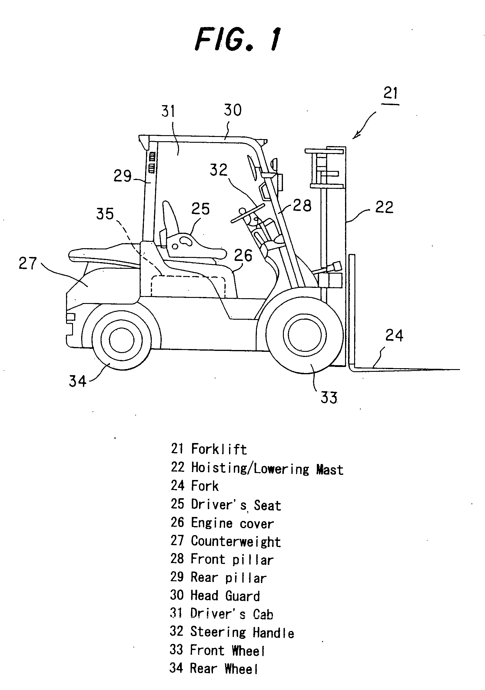
[0038] As shown in FIG. 1, a forklift 21 has a hoisting / lowering mast 22 provided in a front portion of a vehicle, the hoisting / lowering mast 22 being expanded and contracted vertically by a hydraulic cylinder (not shown). A cargo placed on a fork 24 is raised or lowered, together with the fork 24, by the hoisting / lowering mast 22.

[0039] An engine 35, such as a diesel engine or a gasoline engine, is installed at the center of the vehicle. The engine 35 acts as a power source for performing, for example, travel of the vehicle (forklift) and cargo handling work by a hydraulic device such as the hydraulic cylinder. Normally, the engine 35 is covered with an engine cover 26. A driver's seat 25, where an operator sits, is attached to the top surface of the engine cover 26. A counterweight 27 for adjusting a weight balance between...


PUM


Abstract

In an air intake system, a rear tower having a space interiorly is provided on the top surface of a body frame, a rear pillar having a passageway interiorly is mounted on the rear tower, an air intake port communicating with the passageway is provided in the rear pillar, the passageway and the space within the rear tower are connected together, an expansion silencer is connected to the space of the rear tower, and an air cleaner is connected to the expansion silencer. The top surface of a working oil tank is rendered lower than the upper end of a side plate to form a space above the top surface, where the expansion silencer is provided. A base bracket is mounted to the air cleaner, a support bracket is mounted on the side plate, and the base bracket is mounted on the support bracket to support the air cleaner above the expansion silencer.

Description

[0001] The entire disclosure of Japanese Patent Application No. 2003-154599 filed on May 30, 2003, including specification, claims, drawings and summary, is incorporated herein by reference in its entirety. BACKGROUND OF THE INVENTION [0002] 1. Field of the Invention [0003] This invention relates to an air intake system for supplying air to an engine of a forklift, and a forklift equipped with the air intake system. The air intake system is useful when applied in realizing a forklift in which the air intake system is in a compact configuration and an intake noise is markedly reduced. [0004] 2. Description of the Related Art [0005] In an engine-powered forklift, whose vehicle runs by using an engine, such as a diesel engine or a gasoline engine, as a power source and which does cargo handling work by a hydraulic device, the engine is installed at the center of the vehicle, and an air intake system for supplying air to the engine is disposed in a side portion of the vehicle. [0006]FIG...

Claims


Application Information

Patent Timeline
Patent Type & Authority Applications(United States)
IPC IPC(8): B66F9/075B60K13/02B60K13/04B60K13/06F02M35/024F02M35/04F02M35/10F02M35/12F02M35/14F02M35/16
CPCB60K13/02B60K13/06B60Y2200/15B66F9/07595F02M35/14F02M35/10137F02M35/10144F02M35/162F02M35/1266F02M35/04F02M35/10F02M35/12
Inventor ISHIGAMI, AKIHIROABE, MASAFUMIKAMATA, TORUKATAGIRI, HIROTO
Owner MITSUBISHI HEAVY IND LTD
Why Eureka
Try Eureka