Retroreflection information based method for improving lighting system in urban under-crossing short tunnel

A tunnel lighting and retro-reflection technology, applied in outdoor lighting, lighting devices, fixed lighting devices, etc., can solve the problems of short length lighting and transition, easy to induce traffic accidents, narrow separation of opposite lanes, etc., to improve the lighting level and efficiency, mitigating drastic changes in lighting, and avoiding traffic accidents

Inactive Publication Date: 2013-04-24
WUHAN UNIV OF TECH
View PDF4 Cites 24 Cited by
  • Summary
  • Abstract
  • Description
  • Claims
  • Application Information

AI Technical Summary

Problems solved by technology

[0006] Due to the short length of short tunnels under the city, its lighting and transition are not mandatory in national regulations, and the separation zone between opposite lanes is very narrow, it is difficult to physically isolate, so the lighting is often simplified when setting up lighting, resulting in low illumination , the transition of illumination at the entrance and exit is severe, the anti-glare effect is poor, and the hazards of decreased visual function are often underestimated by drivers, which can easily induce traffic accidents

Method used


Image

  • Retroreflection information based method for improving lighting system in urban under-crossing short tunnel
  • Retroreflection information based method for improving lighting system in urban under-crossing short tunnel
  • Retroreflection information based method for improving lighting system in urban under-crossing short tunnel

Examples


Embodiment Construction

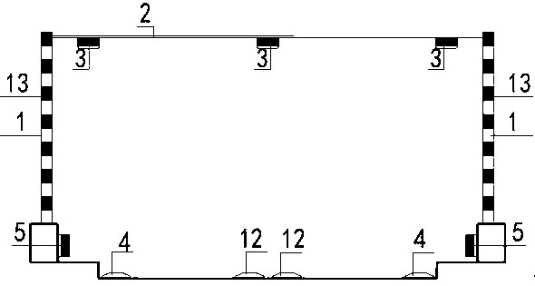
[0038] 1) Use the short lamp post set on the tunnel approach road to lead out the suspension cable from the top or middle of the lamp post, connect the horizontal lamp post to form a suspension cable structure, and coat the lower edge of the lamp post with reflective material to form a yellow and black façade mark; The cable is wrapped with a flexible anti-corrosion material with a diameter of 45mm, and contains conductive cables to provide power for lighting;

[0039] 2) According to the linear shape of the longitudinal section of the tunnel, the light-cutting type lighting fixtures are installed under the suspension cables, and the lateral position of the suspension cable lamps should be kept on the same line as the lighting fixtures in the tunnel as much as possible; It is necessary to ensure that the horizontal lighting of the suspension cable is consistent with the height difference of the road surface;

[0040] 3) The parts of the horizontal suspension cables and lamp p...


PUM


Abstract

The invention provides a retroreflection information based method for improving lighting system in urban under-crossing short tunnel. A wall lamp pole at an approach end of the short tunnel is provided with a variable-height transverse suspension cable, three rows of lamps are transversely arranged on the suspension cable, the longitudinal direction of the lamps is in accordance with the tunnel line shape and the arranging direction of the inside tunnel lamps, facade mark lines are arranged at the lower edge of the lamp pole, side walls of the approach are provided with vertical markings and multiple layers of delineators, transverse optical illusion decelerated markings are arranged on the road surface, and accordingly mid-frequency retroreflection information flow of the tunnel approach is composed. A mid-frequency retroreflection information flow of the under-crossing section of the tunnel is composed by the multiple layers of delineators of the side walls, transverse optical illusion decelerated markings on the road surface, and side wall vertical markings which are arranged on an under-crossing section of the tunnel and extend to a roof. The facade mark lines are arranged on the inner side walls of the tunnel and side walls of the approach at intervals of 1 to 2 meters in the longitudinal direction, while protruding road signs are arranged on road surfaces and road sides, and accordingly the high-frequency retroreflection information flow is composed. By the retroreflection information based method for improving lighting system in urban under-crossing short tunnel, light transition in the exit and entrance of the tunnel can be eased, and smooth transition of vehicle speeds in the exit and entrance of the tunnel is realized through arrangement of multiple retroreflection visual information.

Description

technical field [0001] The invention relates to a method for improving the lighting system of short urban underpass tunnels based on retroreflection information. By improving the lighting level and efficiency of short urban underpass tunnels, the coordination of visual guidance and traffic safety benefits is realized. Background technique [0002] The road characteristics of short tunnels under the city easily lead to typical traffic safety problems. In order to reduce traffic conflicts and improve traffic capacity at urban intersections, some short tunnels are often set up underneath. The short tunnel section formed in this way is generally composed of the underpass section, the approach road of the entrance section, and the approach road of the exit section. However, the length of the tunnel itself is limited by factors such as the nature of the land use, the width of intersecting roads, and the size of the channelization. It is easy for vehicles to accelerate when enter...

Claims


Application Information

Patent Timeline
Patent Type & Authority Applications(China)
IPC IPC(8): F21S8/00F21V19/00E01F9/04E01F9/06E01F9/08F21W131/101E01F9/524E01F9/529E01F9/553E01F9/576E01F9/604
Inventor 杜志刚黄发明陶鹏鹏郑展骥王自入万红亮
Owner WUHAN UNIV OF TECH
Why Eureka
Try Eureka