Blade feeding device

A technology of feeding device and blades, which is applied in the direction of conveyor objects, transportation and packaging, etc. It can solve the problems of falling blades, unable to limit the total amount of blades, and difficult to meet the installation according to the quantity, etc.

Active Publication Date: 2013-05-01
NINGBO SHENGLONG AUTOMOTIVE POWERTRAIN SYSTEM CO LTD
View PDF6 Cites 17 Cited by
  • Summary
  • Abstract
  • Description
  • Claims
  • Application Information

AI Technical Summary

Problems solved by technology

[0003] However, during installation, with the prolongation of the installation time and the increase in the number of installations, memory fatigue is likely to occur, and there may be a phenomenon of under-installation, or there are installation errors that cause blades to fall into the rotor and cannot be found in time. The mai...

Method used


Image

  • Blade feeding device
  • Blade feeding device
  • Blade feeding device

Examples


Embodiment Construction

[0032] The blade feeding device of the present invention will be further described below in conjunction with the accompanying drawings.

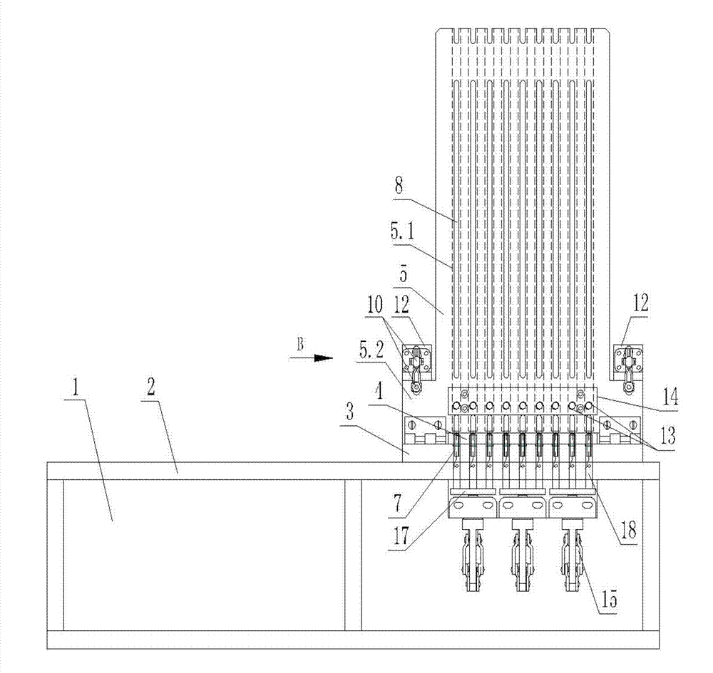
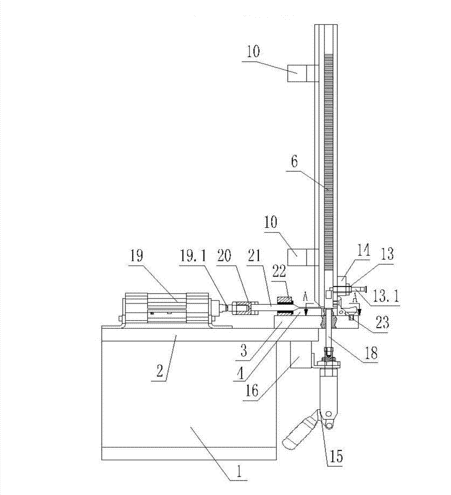
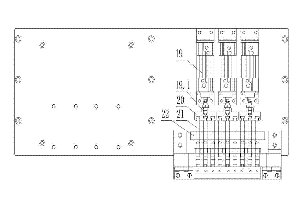
[0033] refer to Figure 1 to Figure 8 , the blade feeding device of the present invention includes a frame 1, a bottom plate 3 installed on the top plate 2 of the frame, a feeding plate 4 installed on the bottom plate 3, located above the feeding plate 4 and hinged on the bottom plate 3 and provided with a trough 5.1 The material box 5 is installed on the left and right ends of the bottom plate 3 so that the material box 5 is in a vertical clamping mechanism, and the material box 5 is installed on the material box 5 to prevent the blade 6 in the hopper 5.1 from falling when the material box 5 is in a vertical state The blocking mechanism is connected with the top plate 2 of the frame so that the blade 6 falling onto the feeding plate 4 is pushed up vertically along the trough 5.1 so that the blocking mechanism blocks the blade 6. The ejectio...


PUM


Abstract

The invention provides a blade feeding device which comprises a rack, a bottom plate, a feed plate, a material tank which is positioned above the feed plate, articulated on the bottom plate and provided with a material groove, clamping mechanisms arranged on the left and right ends of the bottom plate, a stock stop arranged on the material tank, an ejecting mechanism connected with a top plate of the rack, a pusher mechanism arranged on the top plate of the rack and a proximity switch arranged on the feed plate, wherein the material groove is arranged at the back surface of the material tank, extends along the length direction of the material tank and penetrates through the lower end of the material tank; the quantities of a stop rod of the stock stop, an ejecting rod of the ejecting mechanism, a push rod of the pusher mechanism and the proximity switch are the same as that of the material groove and are arranged in one-to-one correspondence; and the feeding device can be used for feeding blades according to the quantity, so that the blades can be arranged in a rotor of a pump body of an oil pump according to the quantity.

Description

technical field [0001] The invention relates to a feeding device, in particular to a blade feeding device capable of sending out blades according to the amount so as to be installed in the rotor of the pump body of the oil pump according to the amount. Background technique [0002] At present, when installing blades in the rotor of the oil pump pump body, it is generally carried out by manual selection and manual installation, that is, one piece is installed and one piece is installed, so that the installation of one rotor blade can be completed after taking 9 pieces in turn and installing them. [0003] However, during installation, with the prolongation of the installation time and the increase in the number of installations, memory fatigue is likely to occur, and there may be a phenomenon of under-installation, or there are installation errors that cause blades to fall into the rotor and cannot be found in time. The main reason for the occurrence is that when selecting bl...

Claims


Application Information

Patent Timeline
IPC IPC(8): B65G47/82
Inventor 李文敏王海良罗玉龙
Owner NINGBO SHENGLONG AUTOMOTIVE POWERTRAIN SYSTEM CO LTD
Why Eureka
Try Eureka