Expansion anchor

A pin and axial technology, applied in the direction of pins, connecting components, mechanical equipment, etc., can solve the problems of increasing the outer diameter of expansion pins, no longer ensuring the clamping effect of the expansion area, fixing the retention force, and increasing the difficulty of expansion pins, etc. Achieve and economical manufacturing effect

Active Publication Date: 2013-05-01
HILTI AG
View PDF6 Cites 1 Cited by
  • Summary
  • Abstract
  • Description
  • Claims
  • Application Information

AI Technical Summary

Problems solved by technology

However, such bulges have the disadvantage that they increase the outer diameter of the expansion pin, thereby increasing the difficulty of inserting the expansion pin into the hole
Furthermore, in the case of enlarged hole diameters, it is no longer possible to ensure a sufficient clamping action of the expansion area and a sufficient fixation and retention of the expansion pins

Method used


Image

  • Expansion anchor
  • Expansion anchor
  • Expansion anchor

Examples


Embodiment Construction

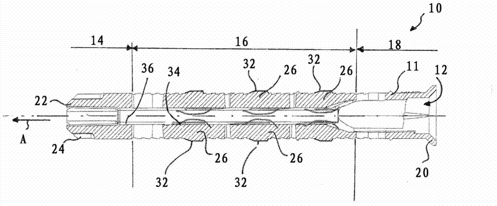
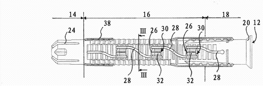
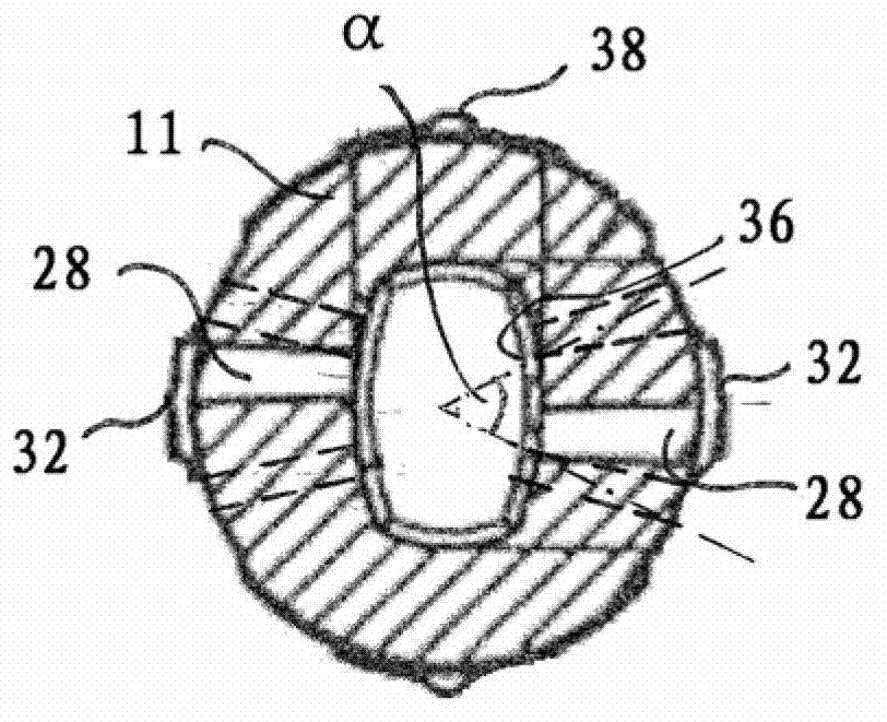
[0024] Figures 1 to 4 Expansion pins 10 shown in are used to secure the component in the substrate. The expansion pin 10 comprises a pin body 11 extending in the axial direction A and having a receptacle 12 (central bore) running in the axial direction A. For installation, the expansion pin 10 is inserted into the borehole of the substrate and is moved into the receptacle 12 through an expansion element (not shown here) in the borehole, expanded and thus clamped in the borehole. . The expansion element is preferably a screw expansion element, which is screwed into the receptacle 12 of the expansion pin 10 . Alternatively, it is also possible to use a snap-in expansion element for this purpose.

[0025] The expansion pin here extends essentially in the axial direction A and has a tip 14 , a clamping region 16 and a head 18 , wherein the receptacle 12 extends through all three regions. Tip 14 serves to center expansion pin 10 during insertion into the substrate borehole and...


PUM


Abstract

The invention relates to an expansion anchor (10) having an anchor body (11) extending in an axial direction (A) and comprising a receptacle (12) for an expansion element, wherein said receptacle runs in an axial direction (A), said expansion anchor having substantially axially running slots (28) for forming radial, elastic regions (26), wherein the anchor wall (34) has a clamping protrusion (32) protruding radially outwardly in the region of at least one slot (28) in an unloaded state of the expansion anchor (10) and the anchor wall (34) closes flush radially to the axially adjacent inner wall region (36) of the expansion anchor (10) on the inside in the region of the clamping protrusion (32).

Description

technical field [0001] The invention relates to an expansion pin comprising an axially extending pin body with an axially running receptacle for an expansion element. Background technique [0002] Dowels (Dübel) are used to fix various components in the substrate. For this purpose, the pins are inserted into boreholes provided in the substrate. The expansion area of ​​the pin is then expanded so that the pin is clamped in the drilled hole. To achieve the expansion of the pin, expansion elements are used, such as screws, which are introduced into the receptacle of the pin and expand the aforementioned expansion region. In particular when screw expansion elements are used, rigid beadings are provided on the outside of the pin, which prevent the pin from turning with it when the screw expansion element is screwed in. However, such bulges have the disadvantage that they increase the outer diameter of the expansion pin, thereby increasing the difficulty of inserting the expans...

Claims


Application Information

Patent Timeline
Patent Type & Authority Applications(China)
IPC IPC(8): F16B13/00F16B13/02
CPCF16B13/126F16B13/124F16B13/0825
Inventor M·斯皮罗维茨
Owner HILTI AG
Why Eureka
Try Eureka