Piloted type pressure reducing valve
A pilot-operated pressure reducing valve and pilot valve technology, which is applied in the field of hydraulic valves, can solve the problems of easy damage, noise, and large impact of pilot valves, and achieve the effects of reducing impact, slowing down moving speed, and increasing service life
- Summary
- Abstract
- Description
- Claims
- Application Information
AI Technical Summary
Problems solved by technology
Method used
Image

Examples
Embodiment 1
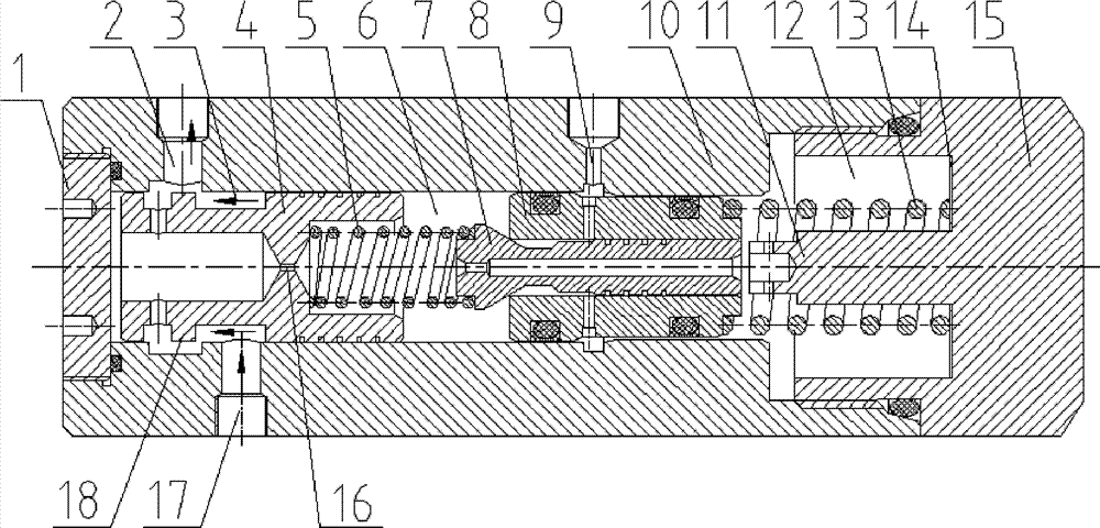
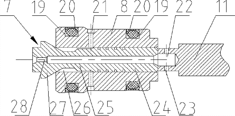
[0025] Such as figure 1 figure 2 As shown, the valve body of the pilot-operated pressure reducing valve includes a valve sleeve 10, a screw plug 11 and a valve cap 15 screwed at both ends of the valve sleeve 10, and a high-pressure oil inlet 17 and a low-pressure oil outlet 2 are arranged on the valve body. A valve cavity is arranged inside the valve body, and a main valve core 4 and a pilot valve are arranged in the valve cavity. The main valve core 4, the pilot valve and the cavity wall of the valve cavity are in sliding fit, and the first cavity 6 is formed between the pilot valve and the main valve core 4. The oil outlet 2 is connected, and the other side of the pilot valve is the second cavity 12 . The pilot valve includes a pilot valve core 7 and a pilot valve seat 8. The center of the pilot valve seat 8 is provided with a pilot valve hole. The pilot valve hole is an axial through hole. The pilot valve core 7 includes a guide part 24 at the head and a cone part 27 at ...
Embodiment 2
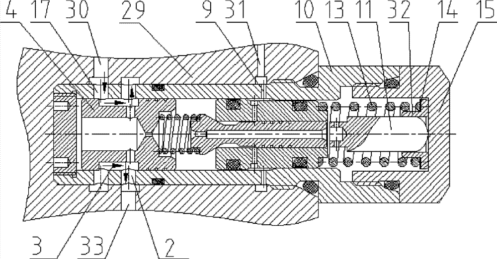
[0028] Such as image 3 As shown, the pressure reducing valve in this embodiment is a plug-in pressure reducing valve. There are threads on the valve sleeve 10, and when it is inserted into the valve block 29, it is screwed with the valve block 29. The high-pressure oil inlet on the valve sleeve 17 and the low-pressure oil outlet 2 communicate with the high-pressure oil circuit 30 and the low-pressure oil circuit 33 on the valve block 29 respectively, and the pilot valve oil outlet 9 on the valve sleeve 10 communicates with the tank oil circuit 31 on the valve block 29 . Compared with the first embodiment, the main difference of this implementation lies in the fixing method of the limit post 11. In this embodiment, the valve body includes a fixed cap 32 arranged in the bonnet 15, and the center of the fixed cap 32 is arranged There is a fixed hole for fixing the limit post 11, the limit post 11 is inserted in the fixed hole and fixedly connected with the fixed cap 32, the oute...
Embodiment 3
[0030] Such as Figure 4 As shown, the pressure reducing valve in this embodiment is a plug-in pressure reducing valve. Compared with Embodiment 2, the difference is that the valve body of the pressure reducing valve in this embodiment includes a valve seat 34, a valve sleeve 10, and a valve cap. 15. The valve sleeve 10 is sleeved on one end of the valve seat 34, and the outside of the end of the valve sleeve 10 sleeved on the valve seat is provided with threads for threaded connection with the valve block 29, and the valve cap 15 is screwed on the other end of the valve sleeve 10 , the main valve core 4 is slidingly arranged in the valve seat, the high-pressure oil inlet 17 is arranged on the side of the valve seat 34, the low-pressure oil outlet 2 is arranged on the end face of the valve seat 34, the annular groove 3 of the main valve core is connected with the The middle hole 37 of the main spool is connected, and the hydraulic oil flows out from the high-pressure oil inlet...
PUM
 Abstract
Description
Claims
Application Information
 - R&D
- Intellectual Property
- Life Sciences
- Materials
- Tech Scout
- Unparalleled Data Quality
- Higher Quality Content
- 60% Fewer Hallucinations
Browse by: Latest US Patents, China's latest patents, Technical Efficacy Thesaurus, Application Domain, Technology Topic, Popular Technical Reports.
© 2025 PatSnap. All rights reserved.Legal|Privacy policy|Modern Slavery Act Transparency Statement|Sitemap|About US| Contact US: help@patsnap.com