Sealing structure for case-penetrating pipelines

A sealing structure and pipeline technology, which is applied in the direction of pipes, mechanical equipment, pipes/pipe joints/pipe fittings, etc., can solve the problems of reducing casing assembly, easy scratches, collision pipelines, etc.

Inactive Publication Date: 2015-04-22
AECC SHENYANG ENGINE RES INST
View PDF6 Cites 0 Cited by
  • Summary
  • Abstract
  • Description
  • Claims
  • Application Information

AI Technical Summary

Problems solved by technology

There are often multiple pipes with different axial and angular positions on the engine passing through the casing. Therefore, when the casing is assembled, the mounting holes of the casing need to be aligned with the positions of each pipe, which not only reduces the assembly of the casing, but also Easy to scratch and collide with the pipeline, which increases the difficulty of assembly work

Method used


Image

  • Sealing structure for case-penetrating pipelines
  • Sealing structure for case-penetrating pipelines

Examples


Embodiment 1

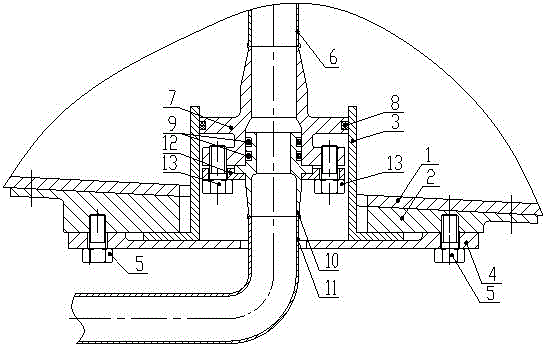
[0019] This embodiment provides a pipeline sealing structure passing through the casing, which is characterized in that it includes a casing 1, a casing mounting seat 2, a floating sleeve 3, a mounting seat pressure plate 4, bolts 5, conduits 6, and special-shaped joints 7. Expansion ring 8, sealing ring 9, movable joint 10, conduit 11, pressure plate 12, bolt 13;

[0020] Among them: the casing mounting seat 2 is welded or riveted on the casing 1, the mounting seat pressure plate 4 is fixed on the casing mounting seat 2 by 4 or 6 bolts 5, and the floating sleeve 3 is connected with the casing mounting seat 2 and the mounting seat. The pressure plate 4 has a gap fit, and can freely move 1~3mm in the circumferential direction. The expansion ring 8 is installed on the special-shaped joint 7, and cooperates with the floating sleeve 3 with a small gap. The conduit 6 and the special-shaped joint 7 are welded together, and the special-shaped joint 7 is lower than the casing. Contain...

Embodiment 2

[0029] This embodiment provides a pipeline sealing structure passing through the casing, which is characterized in that it includes a casing 1, a casing mounting seat 2, a floating sleeve 3, a mounting seat pressure plate 4, bolts 5, conduits 6, and special-shaped joints 7. Expansion ring 8, sealing ring 9, movable joint 10, conduit 11, pressure plate 12, bolt 13;

[0030] Among them: the casing mounting seat 2 is welded or riveted on the casing 1, the mounting seat pressure plate 4 is fixed on the casing mounting seat 2 by 4 or 6 bolts 5, and the floating sleeve 3 is connected with the casing mounting seat 2 and the mounting seat. The pressure plate 4 has a gap fit, and can freely move 1~3mm in the circumferential direction. The expansion ring 8 is installed on the special-shaped joint 7, and cooperates with the floating sleeve 3 with a small gap. The conduit 6 and the special-shaped joint 7 are welded together, and the special-shaped joint 7 is lower than the casing. Contain...


PUM


Abstract

A sealing structure for case-penetrating pipelines is characterized by comprising a case, a case mounting seat, a floating sleeve, a mounting seat pressure plate, first bolts, a first guide pipe, a deformed connector, a packing ring, a seal ring, a moving connector, a second guide pipe, a pressure plate and second bolts. The case mounting seat is welded or riveted on the case. The mounting seat pressure plate is fixed on the case mounting seat through the first bolts. The floating sleeve is in clearance fit with the case mounting seat and the mounting seat pressure plate. The packing ring is disposed on the deformed connector and is in small clearance fit with the floating sleeve. The second guide pipe and the deformed connector are welded integrally. Space between the moving connector and the deformed connector is sealed by the seal ring. The pressure plate is connected with the deformed connector through the second bolts. The moving connector, the second guide pipe and the pressure plate are integrally welded. The sealing structure for case-penetrating pipelines has the advantages that the sealing structure with diameter of phi10-phi24 is mainly used for case-penetrating pipelines on aero-engines, product performance is improved, fitting and tightness of the case with the pipelines are improved, and mounting stress of the pipelines is lowered.

Description

technical field [0001] The invention relates to the field of aero-engines, and in particular provides a pipeline sealing structure passing through the casing. Background technique [0002] The pipes passing through the casing on traditional engines adopt different sealing structures according to their diameters and transmission media. Generally, the pipeline adopts a one-piece sealing structure that passes through the casing, that is, the joints on the pipeline in the casing are exposed outside the casing, and a half-type floating ring is used to match the inner hole of the casing mounting seat. This sealing structure is simple to fix and reliable in sealing, but requires the casing to be a split structure. There are often multiple pipes with different axial and angular positions on the engine passing through the casing. Therefore, when the casing is assembled, the mounting holes of the casing need to be aligned with the positions of each pipe, which not only reduces the as...

Claims


Application Information

Patent Timeline
Patent Type & Authority Patents(China)
IPC IPC(8): F16L5/02
CPCF16L5/025
Inventor 贾铎安喆
Owner AECC SHENYANG ENGINE RES INST
Why Eureka
Try Eureka