Lever arm effect correction method

A lever-arm effect and overload sensor technology, which is applied in the direction of measuring devices, instruments, force/torque/power measuring instrument calibration/testing, etc., can solve problems such as difficult overload correction and large errors

Active Publication Date: 2013-05-08
BEIJING LINJIN SPACE AIRCRAFT SYST ENG INST +1
View PDF3 Cites 4 Cited by
  • Summary
  • Abstract
  • Description
  • Claims
  • Application Information

AI Technical Summary

Problems solved by technology

Differentiating the angular velocity data numerically will introduce a la

Method used


Image

  • Lever arm effect correction method
  • Lever arm effect correction method
  • Lever arm effect correction method

Examples


Embodiment Construction

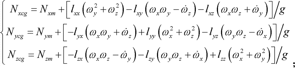
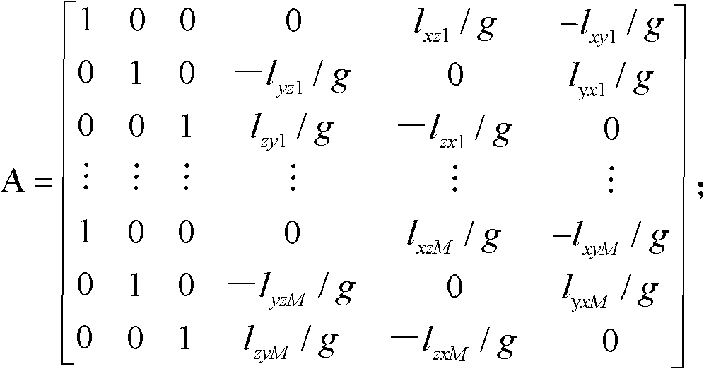
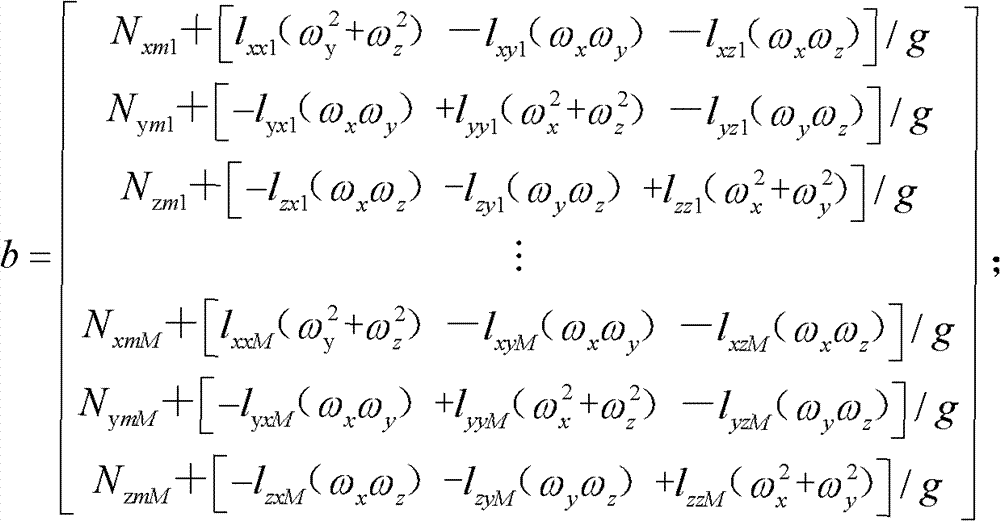
[0026] The present invention comprises the following steps in turn:

[0027] 1) Use M overload sensors, and each overload sensor includes three sensitive heads, which are sensitive to axial, normal and lateral overloads respectively; l xxi , l xyi , l xzi is the component of the position of the axial sensitive head of the i-th overload sensor relative to the coordinates of the center of mass in the x direction, y direction, and z direction, l yxi , l yyi , l yzi is the component of the position of the i-th overload sensor normal direction sensitive head relative to the coordinates x direction, y direction and z direction of the center of mass, l zxi , l zyi , l zzi is the position of the lateral sensitive head of the i-th overload sensor relative to the coordinate x direction, y direction, and z direction components of the center of mass; l xxi , l xyi , l xzi , l yxi , l yyi , l yzi , l zxi , l zyi , l zzi Determined by the installation position of the overload...


PUM


Abstract

The invention relates to a lever arm effect correction method which comprising the following steps sequentially: 1) using M overload sensors, wherein each sensor comprises three sensitive heads which are axial-overload sensitive, normal-overload sensitive and side-overload sensitive, and M>=3; 2) using a used unit to measure angular velocity data; 3) using the overload sensors to measure axial-overload, normal-overload and side-overload; 4) obtaining a coefficient matrix A and a right end vector quantity b; 5) obtaining a transformational matrix Q; 6) obtaining a middle matrix and the changed coefficient matrix A2, wherein A2=AQ, B2=A2 TA2; 7) obtaining a solution vector X; 8) obtaining an axial-overload value X (1), a normal-overload value X (2), and a side-overload value X (3) of a barycenter after elimination of lever arm effect, wherein the X (1), the X (2), and the X (3) are a first element, a second element, and a third element in the X. The lever arm effect correction method uses measured data of a plurality of current devices to eliminate influence of the lever arm effects on the overload sensors, and enables measurement results of the overload sensors to be accurate.

Description

technical field [0001] The invention relates to a correction method of the lever arm effect, in particular to a correction method of the lever arm effect which utilizes a simple and effective engineering method to realize the correction of the lever arm effect. Background technique [0002] When using the overload sensor to measure the overload, if the sensor deviates from the center of mass, due to the influence of the "lever arm effect" rotating around the center of mass, the measured value of the overload sensor will no longer be accurate, and the measured value of the sensor needs to be corrected according to the following formula to obtain Get the overload at the centroid: [0003] N xcg = N xm + [ l ...

Claims


Application Information

Patent Timeline
IPC IPC(8): G01L25/00
Inventor 程璞张鹏宇杨丁王毓栋秦小丽刘明杨明
Owner BEIJING LINJIN SPACE AIRCRAFT SYST ENG INST
Why Eureka
Try Eureka