A Method for Measuring Thin Ice Using Capacitive Thin Ice Sensor with Insert Finger Microstructure

A microstructure and capacitive technology, applied in the field of sensor and sensor technology, can solve the problems of poor accuracy, low detection sensitivity, difficult installation, etc., and achieve the effect of increasing measurement accuracy, reducing misjudgment of icing, and eliminating influence

Inactive Publication Date: 2018-06-12
NO 49 INST CHINESE ELECTRONICS SCI & TECH GRP
View PDF4 Cites 0 Cited by
  • Summary
  • Abstract
  • Description
  • Claims
  • Application Information

AI Technical Summary

Problems solved by technology

[0004] The present invention aims to solve the problems that the existing icing sensors are large in size, difficult to install, low in detection sensitivity and poor in accuracy

Method used


Image

  • A Method for Measuring Thin Ice Using Capacitive Thin Ice Sensor with Insert Finger Microstructure
  • A Method for Measuring Thin Ice Using Capacitive Thin Ice Sensor with Insert Finger Microstructure
  • A Method for Measuring Thin Ice Using Capacitive Thin Ice Sensor with Insert Finger Microstructure

Examples


specific Embodiment approach 1

[0020] Specific implementation mode one: refer to figure 1 and figure 2 Describe this embodiment in detail, one of the methods described in this embodiment adopts

[0021] A method for measuring thin ice with a microstructure capacitive thin ice sensor comprising the following steps:

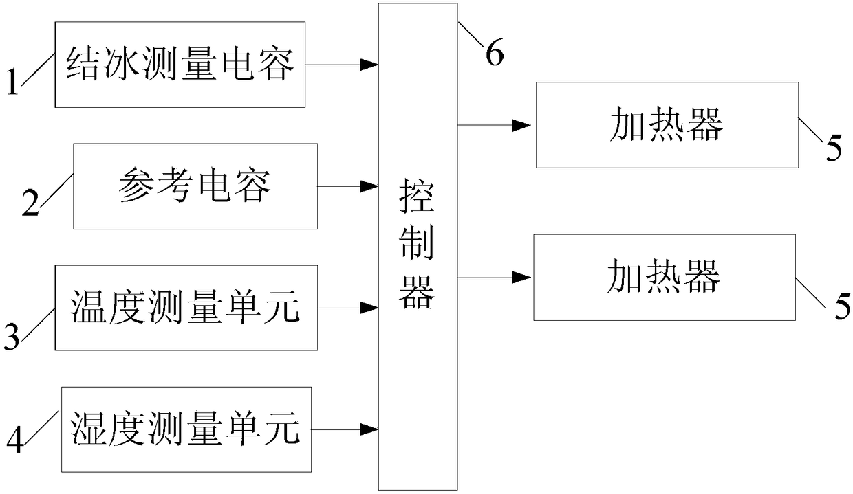
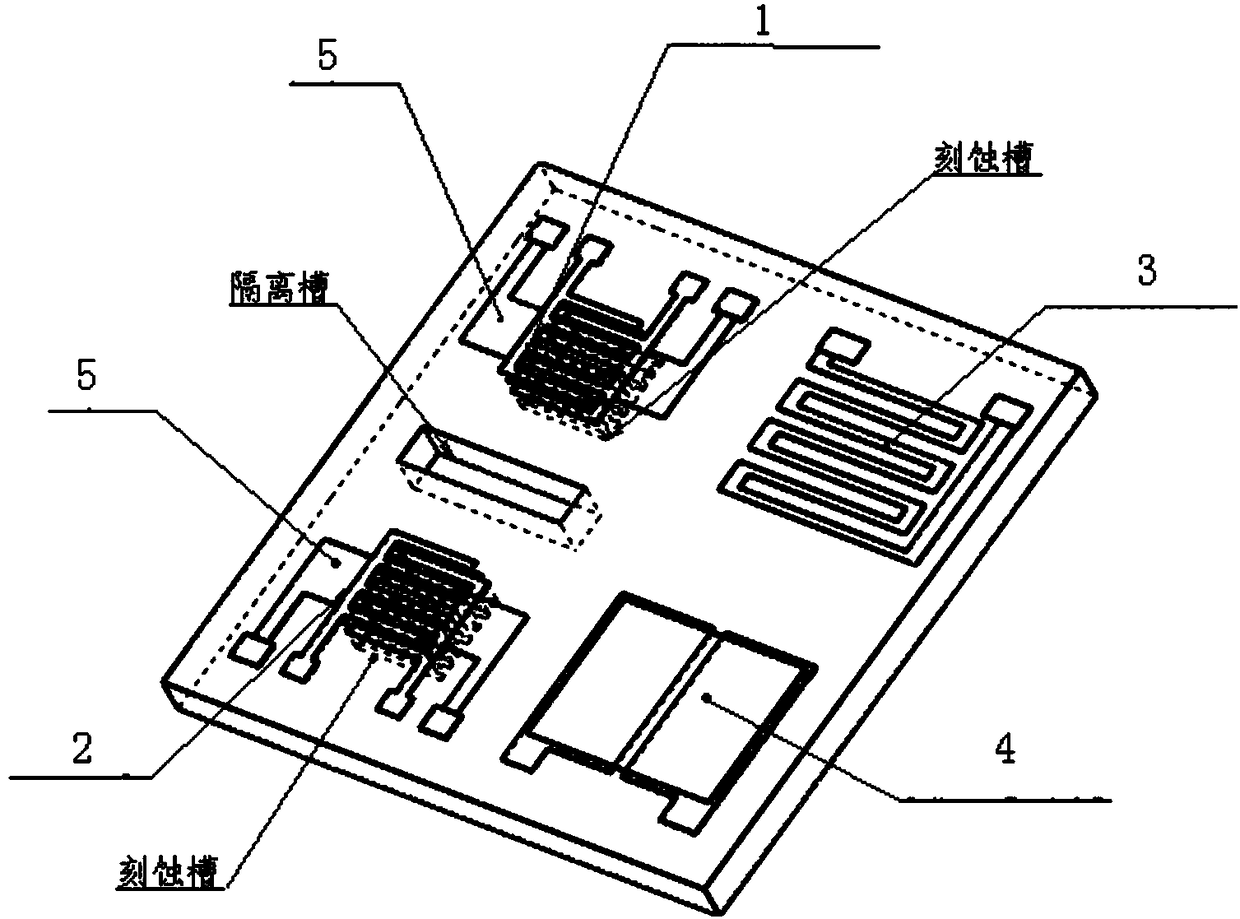
[0022] Step 1. Set the reference capacitor 2, the icing measurement capacitor 1, the temperature measurement unit 3 and the humidity measurement unit 4 on an N-type silicon chip, and use the reference capacitor 2 to measure the capacitance of the air environment; use the icing measurement capacitor 1 to measure Capacitance on the surface of the aircraft; temperature measurement unit 3 is used to measure the temperature of the air; humidity measurement unit 4 is used to measure the humidity of the air;

[0023] Step 2, the controller 6 receives the data of the reference capacitor 2, the data of the icing measurement capacitor 1, the data of the temperature measurement unit 3 and the data of th...

specific Embodiment approach 2

[0026] Specific embodiment 2: This embodiment is a further description of the method for measuring thin ice using the microstructure capacitive thin ice sensor described in specific embodiment 1. In this embodiment, it also includes two heaters 5. Two heaters 5 are respectively arranged at the bottom of the reference capacitor 2 and the icing measurement capacitor 1 for heating, deicing and water removal of the measurement capacitor 1 and the reference capacitor 2 respectively, in preparation for the next measurement.

specific Embodiment approach 3

[0027] Specific embodiment three: This embodiment is a further description of a method for measuring thin ice using a microstructured capacitive thin ice sensor described in specific embodiment one. In this embodiment, the heater 5 is implemented by a heating resistor. , the temperature measurement unit 3 is realized by a platinum thin-film thermistor, and the humidity measurement unit 4 is realized by a humidity sensitive capacitor.


PUM

PropertyMeasurementUnit
electrical resistivityaaaaaaaaaa
relative permittivityaaaaaaaaaa

Abstract

The invention provides a method for measuring thin ice by adopting a finger-inserting micro-structural capacitive thin ice sensor, relating to the technical field of sensors. The method provided by the invention aims to solve the problems of large size, difficulty in mounting, low detection sensitivity and poor accuracy of an existing icing sensor. The method comprises the following steps: receiving data through a controller; judging whether the data of reference capacitance is equal to the data of icing measuring capacitance; if yes, judging that an airplane surface is not iced; if not, judging whether the icing measuring capacitance is 2-78 times of the reference capacitance; if yes, judging that the airplane surface is iced; if not, comparing the icing data with the temperature data and humidity data; judging whether the icing data meets the condition of humidity data with above 70% humidity or temperature below 0 DEG C; if yes, judging that the airplane surface is iced; and if not, judging that the airplane surface is not iced. The thin ice sensor is mounted on the airplane surface and is used for measuring the icing.

Description

technical field [0001] The present invention relates to sensor technology and MEMS technology. In particular, it relates to the principle, structure and manufacturing technology of a capacitive ice sensor with an insertion finger structure, and belongs to the technical field of sensors. Background technique [0002] When an aircraft flies to a certain altitude, the surrounding air humidity is high enough and the temperature is low enough, the surface of the aircraft body may freeze. Even a thin layer of ice can significantly affect the aerodynamic characteristics of aircraft flight. It can reduce the lift force in flight, increase the resistance, deteriorate the endurance performance, and cause the body to shake, making the operation difficult. The impact of icing on the take-off performance is also very serious. It can make the take-off process of the aircraft difficult, and can cause the aircraft to crash after leaving the ground. Therefore, it is necessary to monitor a...

Claims


Application Information

Patent Timeline
Patent Type & Authority Patents(China)
IPC IPC(8): G01N27/22
CPCG01N27/221
Inventor 金建东王明伟王成杨郑丽王亚斌齐虹田雷
Owner NO 49 INST CHINESE ELECTRONICS SCI & TECH GRP
Why Eureka
Try Eureka