A differential pressure detector

A detector, differential pressure type technology, applied in the field of detectors, can solve the problems of low production efficiency, heavy weight, difficult to ensure sealing, etc., to achieve the effect of high sealing degree, simple processing and easy assembly

Active Publication Date: 2022-03-11
SHENYANG GOLDEN TECH PRECISION INSTRUMENT & EQUIPMENT CO LTD
View PDF6 Cites 2 Cited by
  • Summary
  • Abstract
  • Description
  • Claims
  • Application Information

AI Technical Summary

Problems solved by technology

[0003] Therefore, the implementation ratio of the entire gas circuit system of the existing differential pressure detector is complicated. In addition, the solenoid valve will generate heat if it is continuously energized. If the solenoid valve is used in the test gas circuit, the temperature will have a great impact on the test results, which will affect Instrument Accuracy
[0004] figure 1 Shown is a structural diagram of an improved differential pressure detector in the prior art, including a valve seat A, a differential pressure sensor B, a mechanical normally closed air control valve C, a mechanical normally open air control valve D, an inlet The air port E, the reference side F, the workpiece side G and the exhaust port H, the reference side F and the workpiece side G are connected to the reference part and the measured part respectively, and the measured part is realized by controlling the normally closed air control valve C and the normally open air control valve D The test gas circuit action of the test piece and the reference piece is switched at the same time, and the exhaust port H and the air intake port E are connected through the normally closed air control valve C and the normally open air control valve D to overcome the influence of temperature on the test results, but this differential pressure There are still some problems in the type detector, such as: the action of the air control valve is unreliable, the processing of key parts is difficult, the precision of processing and assembly is high, there are many process ports that need to be sealed by the valve seat of the gas circuit, the overall product is large in size and heavy in weight, and it is difficult to assemble. It is difficult to guarantee the overall airtightness of the rear, it is difficult to find small leaks, and the production efficiency is low.

Method used


Image

  • A differential pressure detector
  • A differential pressure detector
  • A differential pressure detector

Examples


Embodiment Construction

[0032]The preferred embodiments of the invention will be described in detail below in conjunction with the accompanying drawings, so that the advantages and features of the invention can be more easily understood by those skilled in the art, so as to define the protection scope of the invention more clearly.

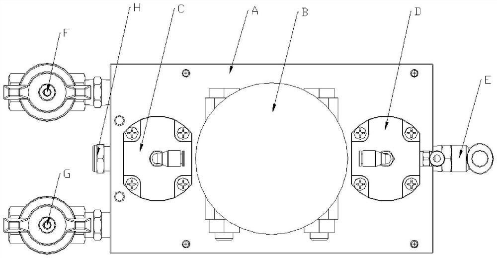
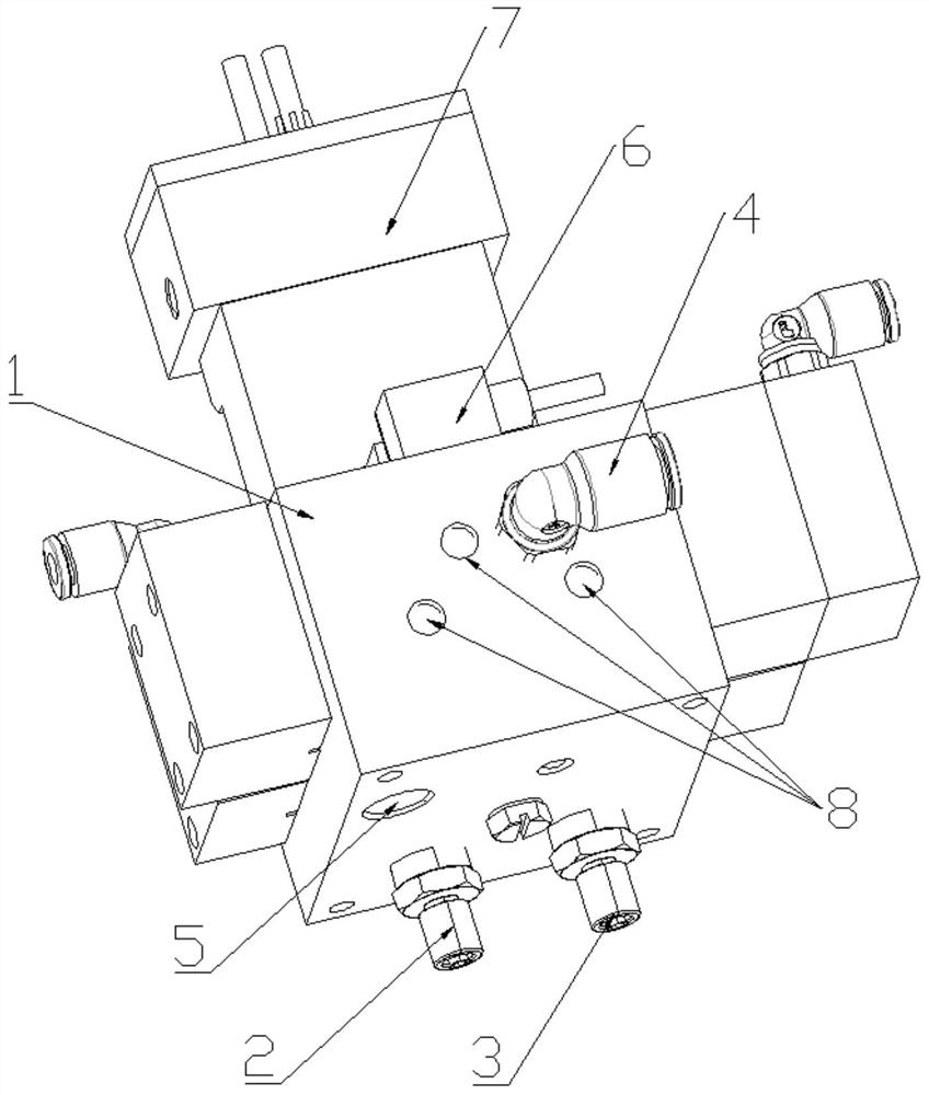
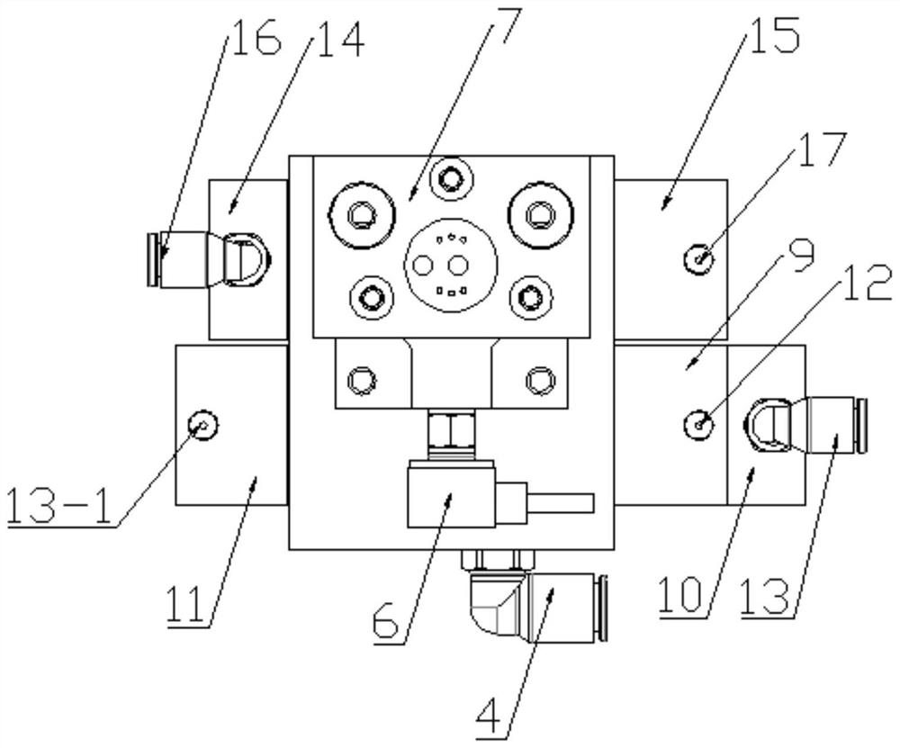
[0033] refer to Figure 2-Figure 13 As shown, the present invention discloses a differential pressure detector, which includes a valve island 1, a pressure sensor 6 and a differential pressure sensor 7, and a first cavity 101, a second cavity 102 and a third cavity are arranged inside the valve island 1 body 103, the second cavity 102 communicates with the first cavity 101 and the third cavity 103, the front side of the valve island 1 is provided with an intake assembly 4 communicating with the first cavity 101, and the lower end of the valve island 1 is provided with There is a reference side port 2, a workpiece side port 3 and an exhaust port 5 communicating with the t...


PUM


Abstract

The invention discloses a differential pressure detector, which comprises a valve island, a pressure sensor and a pressure difference sensor. The inside of the valve island is provided with a first cavity, a second cavity and a third cavity. The second cavity The body communicates with the first cavity and the third cavity, the front side of the valve island is provided with an air intake assembly that communicates with the first cavity, and the lower end of the valve island is provided with a datum that communicates with the third cavity. Side port, workpiece side port and exhaust port, the first cavity is provided with a movable first slide valve assembly, the third cavity is provided with a movable second slide valve assembly, and the valve island A first pneumatic assembly for controlling the movement of the first slide valve assembly is provided, and a second pneumatic assembly for controlling the movement of the second slide valve assembly is provided on the valve island, the pressure sensor communicates with the first cavity, and the The differential pressure sensors communicate with the third cavity through independent channels. The invention eliminates the influence of temperature on the measurement result, and the product has simple processing, high sealing degree, small product volume and convenient assembly.

Description

technical field [0001] The invention relates to the technical field of detectors, in particular to a differential pressure detector. Background technique [0002] The principle of the differential pressure detector is: the internal differential pressure sensor has two ports respectively connected to the test piece and the reference piece, and the same pressure gas is filled in the test piece and the reference piece at the same time, so that the two ends of the differential pressure sensor are balanced. If there is leakage in the tested object, the differential pressure sensor will generate an output signal related to the air leakage per unit time. Whether the test piece is qualified. The entire measurement process is divided into four stages: pressurization, balance, detection and exhaust. The action of the solenoid valve controls the switching of the overall gas circuit and timing. At each stage, the tested part and the reference part must realize different on-off connect...

Claims


Application Information

Patent Timeline
Patent Type & Authority Patents(China)
IPC IPC(8): G01M3/26G01L13/00G01L19/00
CPCG01M3/26G01L13/00G01L19/00
Inventor 范国华
Owner SHENYANG GOLDEN TECH PRECISION INSTRUMENT & EQUIPMENT CO LTD
Why Eureka
Try Eureka