System, device, and method for assisting visual check operation of inspection result

A technique for visual inspection and inspection of results, applied in measurement devices, testing of machine/structural components, etc. using optical devices, which can solve problems such as production efficiency impact and operator operating efficiency reduction.

Active Publication Date: 2013-05-08
ORMON CORP
View PDF10 Cites 8 Cited by
  • Summary
  • Abstract
  • Description
  • Claims
  • Application Information

AI Technical Summary

Problems solved by technology

Therefore, in order to immediately specify which part of the actual substrate the defective part corresponds to, it is not sufficient to display only the image of the range centered on the defective part
As a result, operators are less productive and can have a dramatic impact on overall productivity

Method used


Image

  • System, device, and method for assisting visual check operation of inspection result
  • System, device, and method for assisting visual check operation of inspection result
  • System, device, and method for assisting visual check operation of inspection result

Examples


Embodiment Construction

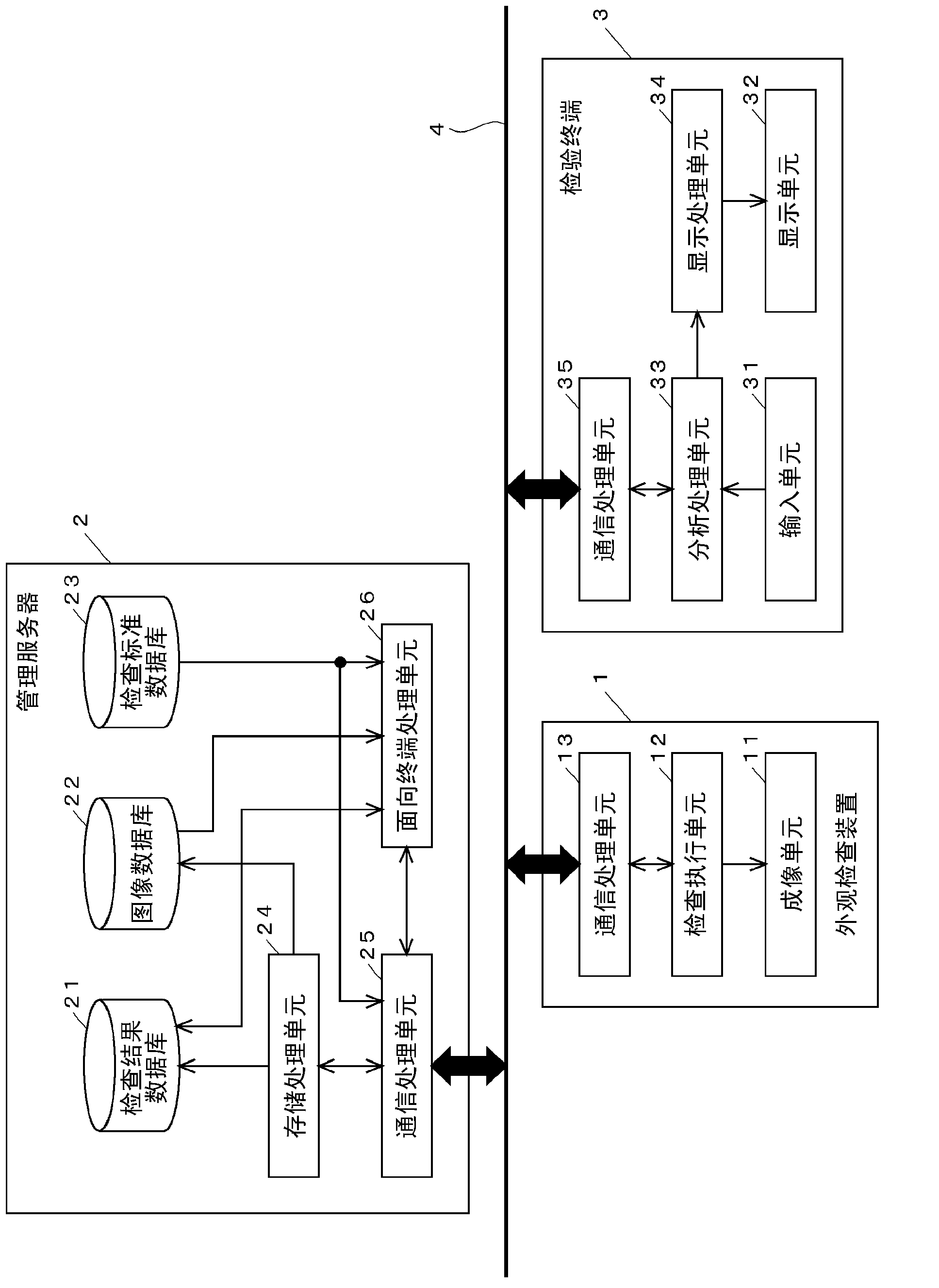
[0033] figure 1 is a functional block diagram showing a configuration example of a system for inspecting a component-mounted substrate.

[0034] This embodiment is an embodiment in which automatic appearance inspection is performed on an object that is a component-mounted substrate (hereinafter, simply referred to as "substrate") completed through the respective steps, namely, a solder printing step, a component mounting step, and a reflow step, The operator is then allowed to visually inspect the areas determined to be defective by said inspection. This embodiment includes an appearance inspection device 1, a management server 2, and a terminal device 3 for inspection operations (hereinafter, referred to as "inspection terminal 3"). The respective devices 1, 2, and 3 are connected to each other via a local area network (LAN) line 4; however, the inspection terminal 3 and the appearance inspection device 1 do not directly communicate with each other, but information is exchan...


PUM


Abstract

With regard to a target (board) to which an automatic appearance inspection is completed, an image used in the inspection is stored, measurement data obtained by measurement processing in the inspection is stored in association with positional information of a measurement target region, and by using these pieces of stored information, an image for assisting an operation of visually checking an actual state of a specific inspection target region is displayed. This image corresponds to an area equivalent to a part of the board, and includes the checking target component100. For the checking target component100 in the image, marking by a frame UW and lines L1 and L2 is implemented. Moreover, feature regions which are visually recognizable and have intrinsic features(101,102,103) are extracted so as to surround a periphery of the checking target component.

Description

technical field [0001] The present invention relates to a system for assisting an operation of inspecting an inspection result obtained by automatic appearance inspection using an image by visually recognizing an actual inspection target, an apparatus for the assistance, and an application for in this auxiliary method. Background technique [0002] At a manufacturing site of a component-mounted board, the presence of components, the state of solder fillet, etc. are inspected by an automatic visual inspection device, after which an operator visually inspects components finally determined to be defective. Also, for correctable parts among parts defined as defective, the operator can manually correct these parts while checking their status. [0003] As a conventional example of an apparatus performing an operation of visually recognizing a defective portion, there is an apparatus in which a magnifying glass is arranged above a stage supporting each substrate as an inspection t...

Claims


Application Information

Patent Timeline
Patent Type & Authority Applications(China)
IPC IPC(8): G01N21/88G01N21/956
CPCG06K9/03G01N21/95684G06T7/001H05K13/08G01N2021/95638G06T2207/30141G01N21/95607G01M11/00G01N21/9501G06T2200/24G06T7/0004G01B11/00G01N21/88
Inventor 川田哲博
Owner ORMON CORP
Why Eureka
Try Eureka