Event data recorder and image record module

A recorder and image technology, applied to instruments, time registers, registering/indicating the operation of vehicles, etc., can solve problems such as consumption, failure to start vehicles smoothly, short standby time, etc.

Active Publication Date: 2013-05-08
PIXART IMAGING INC
View PDF6 Cites 7 Cited by
  • Summary
  • Abstract
  • Description
  • Claims
  • Application Information

AI Technical Summary

Problems solved by technology

Therefore, the driving recorder 100 of the prior art has a very short standby time in the parking mode, which may consume a large amount of batte

Method used


Image

  • Event data recorder and image record module
  • Event data recorder and image record module

Examples


Embodiment Construction

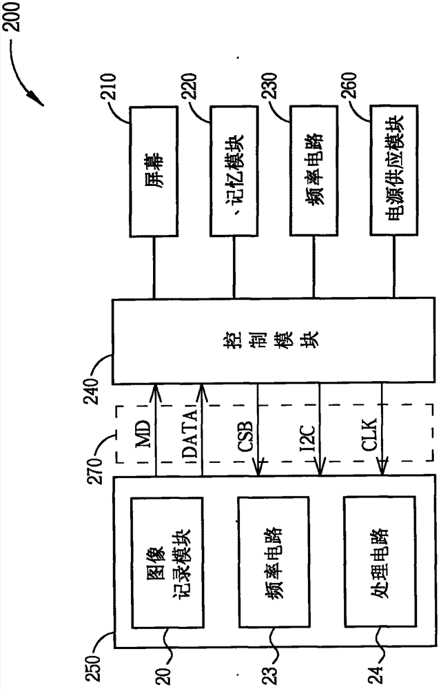
[0023] figure 2 It is a functional block diagram of the driving recorder 200 in the present invention. The driving recorder 200 includes a screen 210 , a memory module 220 , a frequency circuit 230 , a control module 240 , an image recording module 250 , a power supply module 260 , and a transmission interface 270 . The screen 210 can be a liquid crystal display screen for displaying real-time images or previously recorded images. The memory module 220 may include a buffer memory, a built-in memory / hard disk, or a module capable of supporting an external mobile memory / hard disk for storing image data or related settings when the driving recorder 200 operates. The frequency circuit 230 can be a quartz crystal oscillator, which is used to provide a reference frequency signal required for the operation of the driving recorder 200 . The control module 240 can be a back-end control chip for controlling the operation of various components in the driving recorder 200 . The image ...


PUM


Abstract

The invention discloses an event data recorder and an image record module. The event data recorder can be operated in a driving mode and a parking mode. In the driving mode, the event data record performs a high-quality video function by using the image record module. In the parking mode, the event data recorder firstly starts the image record module regularly to detect a specific event, and performs a low-quality video function after the specific event is detected, so that the event data recorder disclosed by the invention has the advantages of low energy consumption and a variety of modes.

Description

technical field [0001] The invention relates to a driving recorder and an image recording module, in particular to a low-energy driving recorder and an image recording module that can increase the standby time in a parking mode. Background technique [0002] Since the invention of automobiles, the probability of traffic accidents has also increased with the increase in the number of vehicles. Traffic accidents are mostly caused by human negligence or driving violations. In order to clarify the responsibility for the accident, more and more car owners will install event data recorders (EDR) on their vehicles. The driving recorder usually provides two modes: in the driving mode, it can record the driving process, so it can provide on-site evidence in the event of an emergency; Provide evidence at impact. [0003] figure 1 It is a functional block diagram of the driving recorder 100 in the prior art. The driving recorder 100 includes a screen 110 , a memory module 120 , a f...

Claims


Application Information

Patent Timeline
IPC IPC(8): G07C5/00
Inventor 许恩峯高铭璨
Owner PIXART IMAGING INC
Why Eureka
Try Eureka