
Button

A key and key cap technology, applied in electrical components, electrical switches, circuits, etc., can solve the problems of shortened service life and fatigue status of key 1, and achieve the effect of extending service life

Active Publication Date: 2013-05-08
DARFON ELECTRONICS (SUZHOU) CO LTD +1
View PDF4 Cites 10 Cited by
  • Summary
  • Abstract
  • Description
  • Claims
  • Application Information

AI Technical Summary

Problems solved by technology

Since the elastic member 18 is often made of rubber, the rubber will be fatigued under long-term use, thereby shortening the service life of the button 1

Method used


Image

  • Button
  • Button
  • Button

Examples


Embodiment Construction

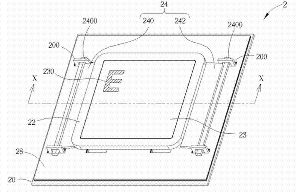
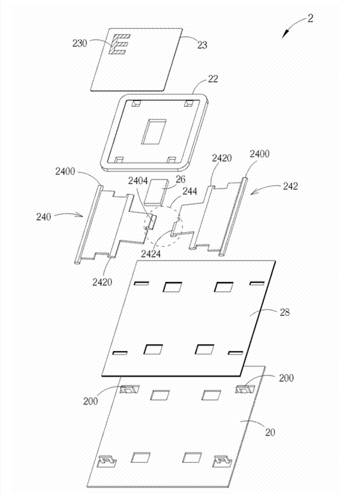
[0032] see Figure 2 to Figure 5 , figure 2 is a perspective view of an embodiment of the button of the present invention, image 3 for figure 2 The explosion diagram of button 2 in Figure 4 for figure 2 The cross-sectional view of button 2 along the line X-X in Figure 5 for image 3 The cross-sectional view of the keycap 22 when it is pressed. like Figure 2 to Figure 5 As shown, the key 2 includes a base plate 20 , a keycap 22 , a cover plate 23 , a supporting device 24 and a circuit board 28 . In practical applications, the circuit board 28 may be a thin film circuit board, but not limited thereto.

[0033] The supporting device 24 is disposed between the bottom plate 20 and the keycap 22 , and is rotatably connected to the keycap 22 and the bottom plate 20 respectively. In this embodiment, the supporting device 24 may include a first supporting member 240 and a second supporting member 242 . The first support 240 and the second support 242 respectively inclu...


PUM


Abstract

The invention relates to a button. The button comprises a baseplate, a button cap, cover plate and a supporting device. The cover plate is arranged above the button cap and is made of magnetic materials. The supporting device is arranged between the baseplate and the button cap and is respectively connected with the button cap and the baseplate in a rotating mode. The button cap has a first magnetic area, and the supporting device has a second magnetic area, wherein the position of the first magnetic area is corresponding to the position of the second magnetic area. When the button cap is not pressed, the magnetic attractive force between the first magnetic area and the second magnetic area enables the button cap to be kept in an unpressed position. When the button cap is pressed by external force, the button cap is moved from the unpressed position to a pressed position along with the supporting device. When the external force is released, the magnetic attractive force enables the first magnetic area to be close to the second magnetic area, so that the button cap can be moved back to the unpressed position from the pressed position along with the supporting device. The button utilizes the magnetic attractive force to enable the button cap to be shifted between the unpressed position and the pressed position along with the supporting device without installing elastic pieces, so the service life of the button can be effectively prolonged.

Description

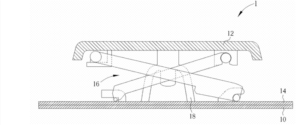
technical field [0001] The present invention relates to a button, in particular to a button which utilizes magnetic attraction force to move the keycap along with the supporting device between a non-pressed position and a pressed position. Background technique [0002] As far as current personal computer usage habits are concerned, the keyboard is one of the indispensable input devices for inputting characters, symbols or numbers. Not only that, but all consumer electronic products in daily life or large-scale processing equipment used in the industry need to be equipped with a key structure as an input device to operate the above-mentioned electronic products and processing equipment. [0003] see figure 1 , figure 1 It is a schematic cross-sectional view of a button in the prior art. like figure 1 As shown, the button 1 includes a bottom plate 10 , a keycap 12 , a circuit board 14 , a supporting device 16 and an elastic member 18 . The circuit board 14 is disposed on ...

Claims


Application Information

Patent Timeline
IPC IPC(8): H01H13/86H01H13/14
Inventor 陈基煌周瑞崇
Owner DARFON ELECTRONICS (SUZHOU) CO LTD
Learn More