Chemical liquid recovery device

A technology for recycling device and chemical liquid, applied in the field of chemical liquid recycling device, can solve the problems of dilution, chemical liquid is polluted, cannot be reused, etc., and achieves the effect of automatic conversion, rapid response, and reduction of pollution and dilution problems.

Active Publication Date: 2015-07-22
SHENYANG KINGSEMI CO LTD
View PDF2 Cites 0 Cited by
  • Summary
  • Abstract
  • Description
  • Claims
  • Application Information

AI Technical Summary

Problems solved by technology

[0003] In order to solve the problem that the chemical liquid cannot be reused due to contamination and dilution during the recovery process, the object of the present invention is to provide a chemical liquid recovery device with a liftable CUP

Method used


Image

  • Chemical liquid recovery device
  • Chemical liquid recovery device

Examples


Embodiment Construction

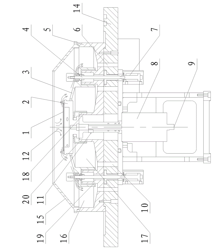
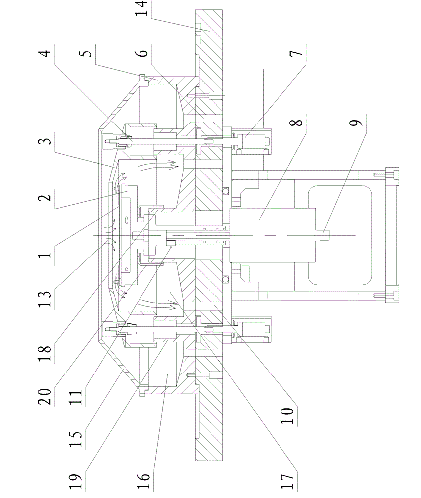
[0016] The present invention will be described in further detail below in conjunction with the accompanying drawings.

[0017] like figure 1 , figure 2 As shown, the present invention includes a wafer 1, a wafer stage 2, a CUP3, a liquid contact tank 5, a cylinder 7, a motor 8 and a table top 14, wherein the liquid contact tank 5 is fixed on the upper surface of the table top 14, and the liquid contact tank 5 is The bottom surface extends upward in the axial direction, forming a hollow first protrusion 18 and a second protrusion 19 from the inside to the outside. Line, the second protrusion 19 is located on the periphery of the first protrusion 18, and is arranged concentrically with the first protrusion 18, an inner groove 17 is formed between the first protrusion 18 and the second protrusion 19, and the second protrusion 19 is connected to the An outer tank 16 is formed between the outer walls of the liquid tank 5, and the outer tank 16 and the inner tank 17 are independe...


PUM


Abstract

The invention belongs to the field of wet processing of chips in the semiconductor industry, and particularly relates to a chemical liquid recovery device with a liftable CUP. The chemical recovery device comprises a supporting stage used for fixing and rotating a chip, a CUP, a liquid connecting groove, a cylinder, a motor and a countertop. The liquid connecting groove is installed on the countertop and the supporting stage which is driven by the dynamo is installed inside the liquid connecting groove. The elevated CUP which is driven by the cylinder is arranged between the liquid connecting groove and the supporting stage. The liquid connecting groove is divided into an outer groove used for recycling the chemical liquid and an inner groove used for recycling the cleaning liquid by the CUP. Each groove is provided with an outlet. The chemical liquid recovery device controls the separation of the chemical liquid and the cleaning liquid by the way of lifting the CUP. The requirement of recycling chemical liquid can be met in the wet processing through different channels to recycle, and the problems of the pollution of the chemical liquid and being diluted are reduced to a great extent.

Description

technical field [0001] The invention belongs to the field of wafer wet processing in the semiconductor industry, in particular to a chemical liquid recovery device with a liftable CUP. Background technique [0002] At present, chemical liquids are often used in the wafer wet processing process in the semiconductor industry, and how to achieve pollution-free and dilution-free recycling and reuse of chemical liquids is an inevitable problem. In the prior art, the recovery of the chemical liquid is difficult, and the recovered chemical liquid may be contaminated and diluted. Therefore, how to avoid contamination and dilution of the chemical solution during the recycling process has become an urgent problem to be solved. SUMMARY OF THE INVENTION [0003] In order to solve the problem that the chemical liquid cannot be reused due to contamination and dilution during the recovery process, the purpose of the present invention is to provide a chemical liquid recovery device with ...

Claims


Application Information

Patent Timeline
Patent Type & Authority Patents(China)
IPC IPC(8): H01L21/67
Inventor 谷德君卢继奎
Owner SHENYANG KINGSEMI CO LTD
Why Eureka
Try Eureka