Vehicle-mounted antenna and manufacturing method thereof

A technology for a vehicle-mounted antenna and a manufacturing method, which is applied in directions such as antennas suitable for movable objects, radiating element structure forms, and radiating element structure forms, etc. The effect of bandwidth, good antenna performance and high antenna gain

Active Publication Date: 2013-05-08
苏州中兴联精密工业有限公司
View PDF10 Cites 13 Cited by
  • Summary
  • Abstract
  • Description
  • Claims
  • Application Information

AI Technical Summary

Problems solved by technology

[0003] The problem solved by the invention is that the existing antennas are easy to break, generate noise and have poor performance

Method used


Image

  • Vehicle-mounted antenna and manufacturing method thereof
  • Vehicle-mounted antenna and manufacturing method thereof
  • Vehicle-mounted antenna and manufacturing method thereof

Examples


Embodiment Construction

[0023] In order to describe the technical content, structural features, achieved goals and effects of the present invention in detail, the following will be described in detail in conjunction with the embodiments and accompanying drawings.

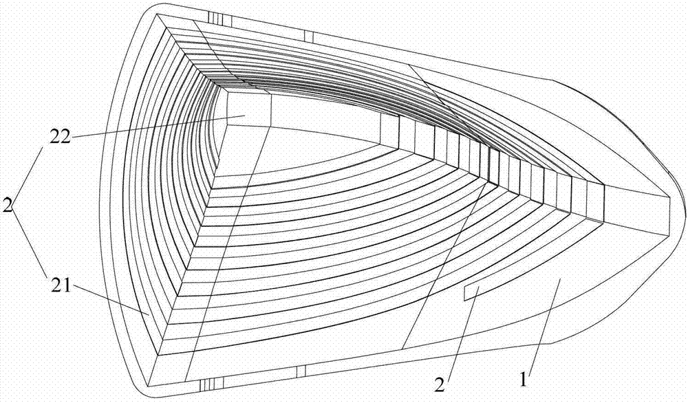
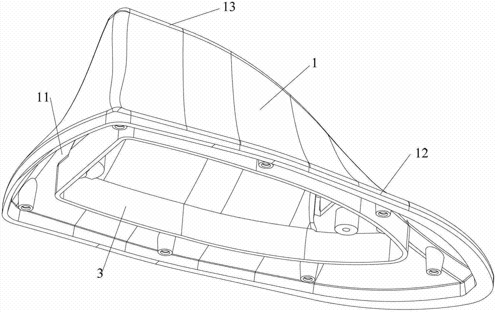
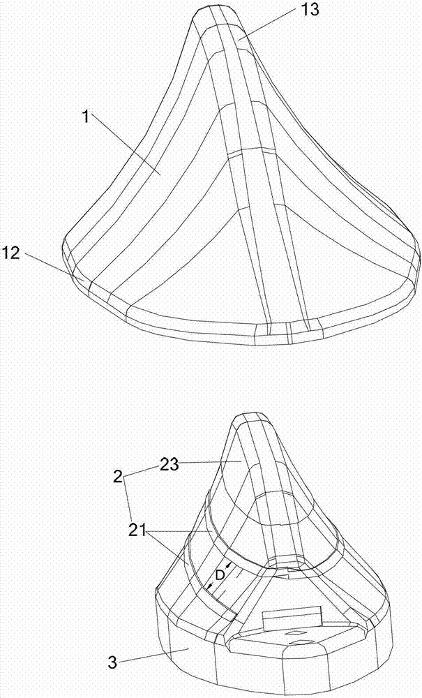
[0024] see figure 1 , which is a schematic structural diagram of the first embodiment of the vehicle-mounted antenna of the present invention. The vehicle-mounted antenna includes a housing 1 made of plastic and an antenna radiating portion 2 disposed on the inner surface of the housing 1 .

[0025] The housing 1 is shaped like a shark's fin and has a cavity (not labeled). The antenna radiating part 2 is spirally wound on the inner wall of the housing 1 . Specifically, it is formed on the inner wall surface of the cavity of the housing 1 through a laser direct structuring process (Laser Direct structuring, LDS for short). The following steps can be taken to form the antenna radiating part 2: (1) Injection molding the housing 1 with a ca...


PUM

PropertyMeasurementUnit
Line widthaaaaaaaaaa
Pitchaaaaaaaaaa
Lengthaaaaaaaaaa

Abstract

The invention discloses a vehicle-mounted antenna and a manufacturing method of the vehicle-mounted antenna. The vehicle-mounted antenna comprises a shell body and an antenna radiating portion, wherein the shell body is provided with a cavity, the antenna radiating portion is arranged in the cavity, and the antenna radiating portion is formed through the laser direct structuring (LDS) technology. Because the cavity of the shell body of the vehicle-mounted antenna is provided with the antenna formed through the LDS technology, the antenna is not high, and not easy to break off, and generates no noise. The antenna is formed through the LDS technology, and is in an integrated structure. Unlike a bar-like antenna which is directly bent in the prior art, the vehicle-mounted antenna is good in performance.

Description

technical field [0001] The invention relates to an antenna, in particular to a vehicle-mounted antenna and a manufacturing method of the vehicle-mounted antenna applied to vehicles and other transportation means. Background technique [0002] The traditional car antenna (including AM / FM) is a rod antenna, usually in the form of a spiral wound by copper wire, with a height of about 400 mm or more. , the antenna will generate noise, seriously affecting the reception effect. However, although some vehicle-mounted antennas use low-profile antennas, they usually bend the rod-shaped helical antenna directly, so that although the height of the antenna is reduced, the electrical performance of the antenna (including bandwidth, gain) is very poor, and even the antenna cannot be used. This method of reducing the height by bending the rod-shaped helical antenna has limited effect after all, and cannot meet the requirements of miniaturization of the antenna. Contents of the invention...

Claims


Application Information

Patent Timeline
IPC IPC(8): H01Q1/38H01Q1/40H01Q1/42H01Q1/32
Inventor 张亚斌王宏军王清李延洪
Owner 苏州中兴联精密工业有限公司
Why Eureka
Try Eureka