
Backup power control system

A power control and backup technology, applied in power network operating system integration, emergency power arrangement, information technology support system, etc., can solve problems such as high cost and design difficulties, prevent current backflow, provide isolation protection, solve The effect of excessive power consumption

Active Publication Date: 2013-05-08
PEGATRON
View PDF3 Cites 9 Cited by
  • Summary
  • Abstract
  • Description
  • Claims
  • Application Information

AI Technical Summary

Problems solved by technology

Design difficulties and high costs for downsized system designs

Method used


Image

  • Backup power control system
  • Backup power control system
  • Backup power control system

Examples


Embodiment Construction

[0021] Reference will now be made in detail to embodiments of the invention, examples of which are illustrated in the accompanying drawings. In addition, wherever possible, elements / components using the same reference numerals in the drawings and embodiments represent the same or similar parts.

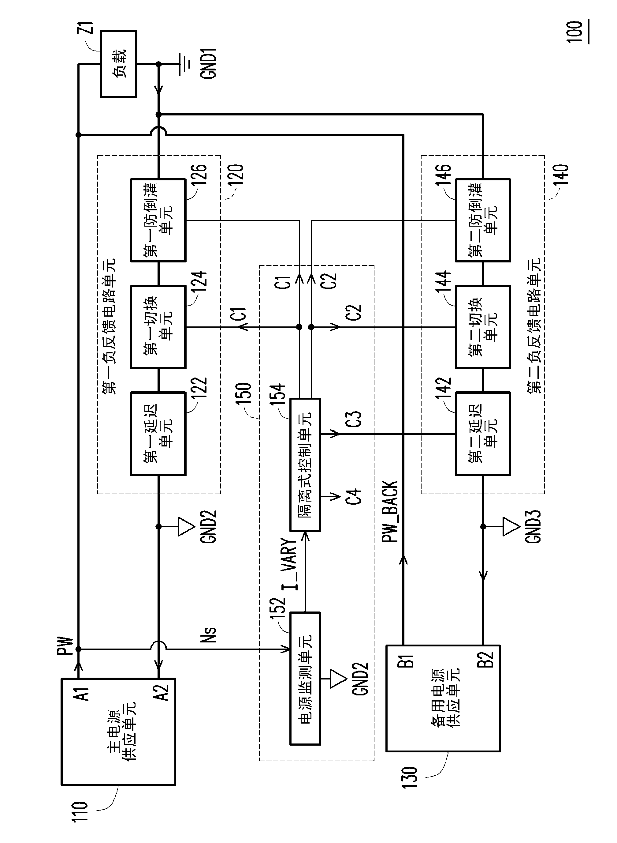
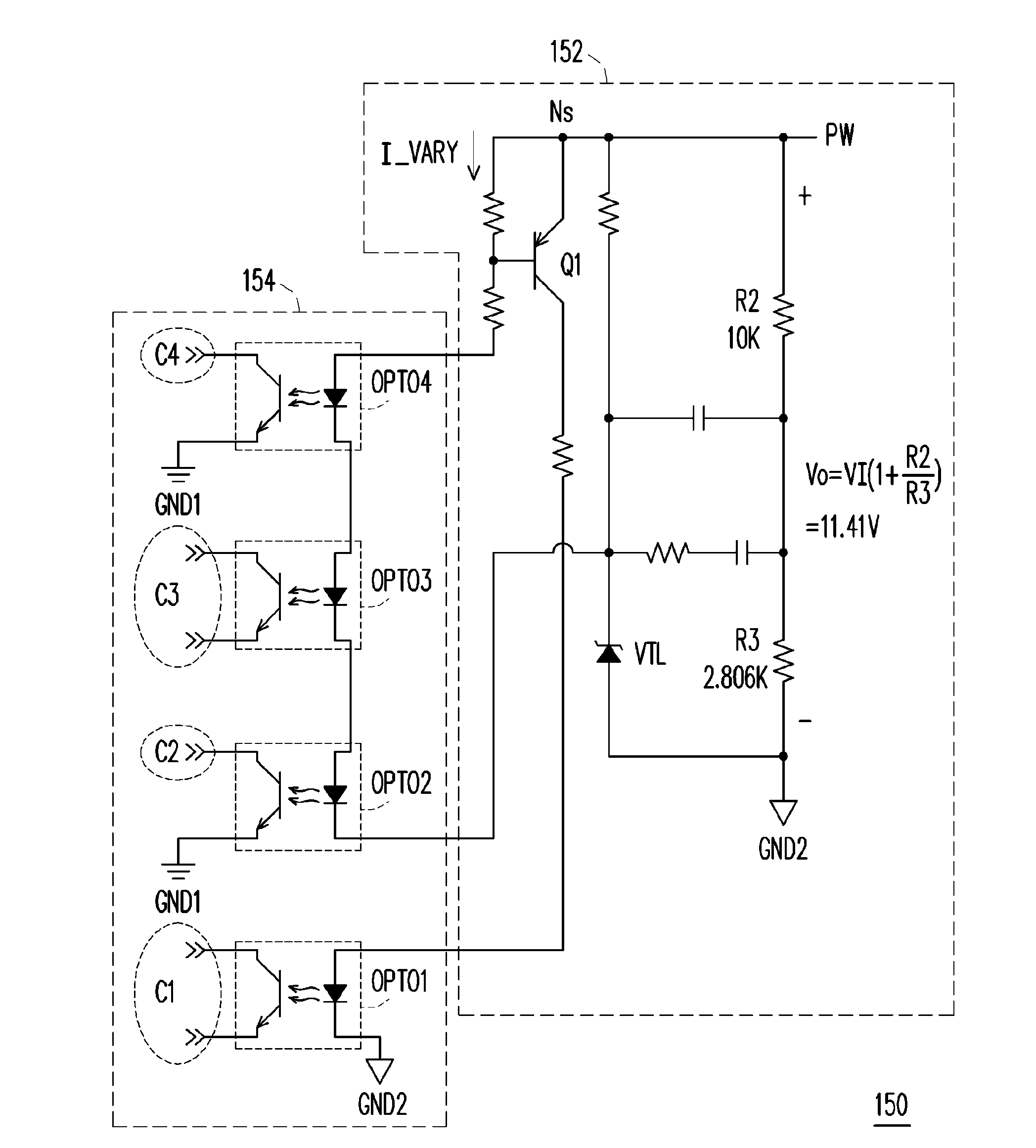
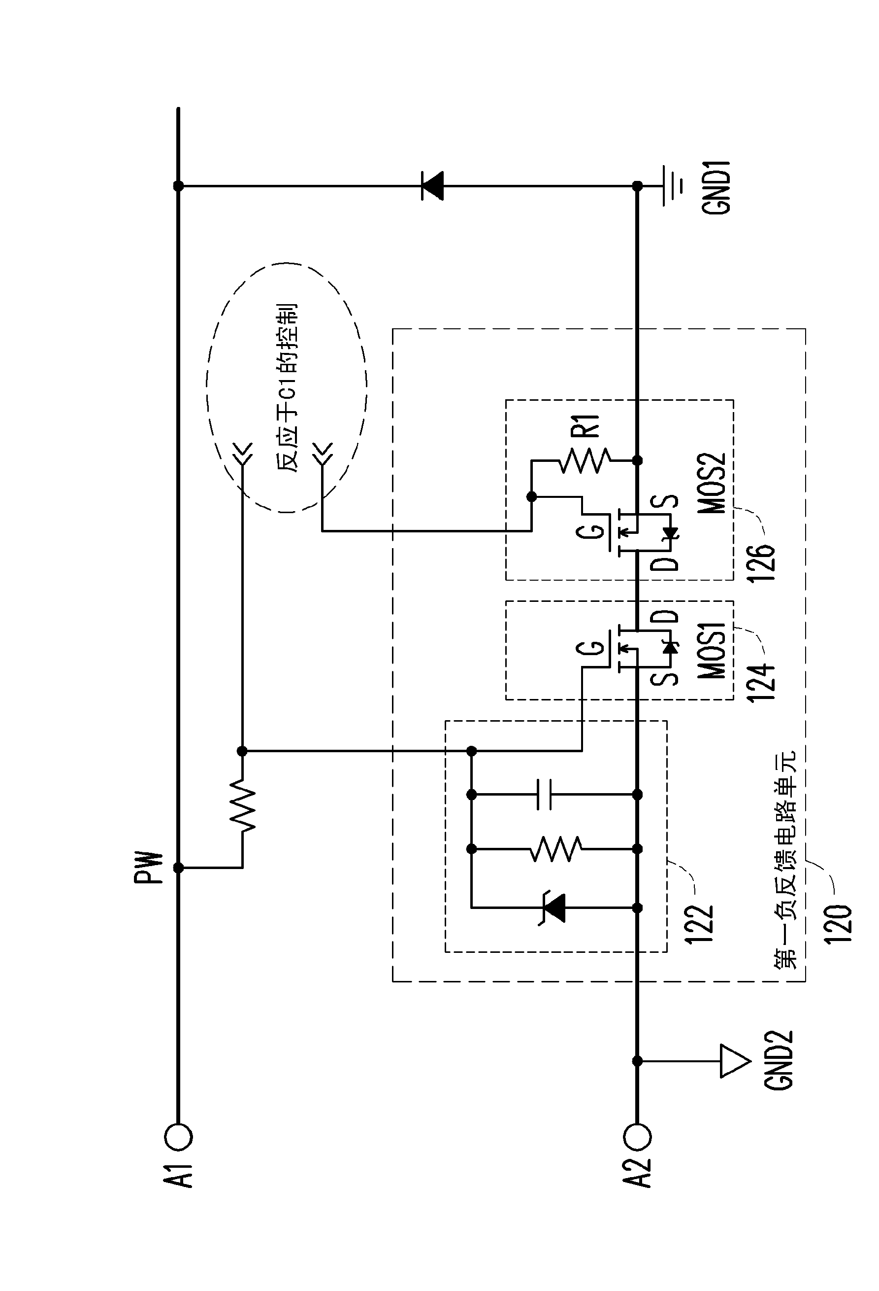
[0022] figure 1 is a schematic diagram of a redundant power control system 100 according to an embodiment of the present invention. see figure 1 . The backup power control system 100 includes a main power supply unit 110 , a first negative feedback circuit unit 120 , a backup power supply unit 130 , a second negative feedback circuit unit 140 and a control unit 150 . The main power supply unit 110 is used to output the main power PW, so as to supply power to the load Z1. The main power supply unit 110 may utilize, for example, an AC (Alternating Current, AC)-to-DC supply unit to generate a stable main power PW. For example, the main power supply unit 110 may be an AC-12V supply u...


PUM


Abstract

The invention provides a backup power control system, comprising a main power supply unit, a first negative feedback circuit unit, a standby power supply unit, a second negative feedback circuit unit, and a control unit. The main power supply unit is suitable for outputting a main power. The standby power supply unit is suitable for outputting a standby power. The control unit switches the first negative feedback circuit unit and the second negative feedback circuit unit to be turned on or not to be turned on in response to whether a normal power supply signal of the main power is received. When the normal power supply signal is received, the control unit enables the first negative feedback circuit unit to be turned on and enables the second negative feedback circuit unit not to be turned on. The backup power control system of the invention can effectively resolve the problem derived from oversize power consumption of a traditional diode.

Description

technical field [0001] The invention relates to a power control technology, and in particular to a backup power control system. Background technique [0002] For the existing redundant power supply architecture, please refer to the "redundant power supply system" in Taiwan Patent Announcement No. I331714. It can be seen from the content disclosed in the previous application that traditional diodes are used as the switch and conduction of the power backup. This will lead to excessive power consumption on the diode, so there will be overheating and reduced power conversion efficiency, and it may also lead to an increase in the damage rate of components on the system due to poor heat dissipation. [0003] Another existing redundant power supply architecture can refer to the "Active OR Gate Processing Controller for Redundant Power Supply System" in Taiwan Patent Announcement No. I271910. It can be seen from the content disclosed in the previous case that isolation (Isolation) c...

Claims


Application Information

Patent Timeline
Patent Type & Authority Applications(China)
IPC IPC(8): H02J9/04
CPCH02J9/04H02J9/06Y02B70/30Y04S20/20
Inventor 陈浩杰
Owner PEGATRON
Learn More