Rotor And Motor
A technology for rotors and rotor cores, which is applied to electric components, magnetic circuit rotating parts, electrical components, etc., can solve the problems of increasing the number of components and assembly hours, and achieve the effect of reducing the number of components
- Summary
- Abstract
- Description
- Claims
- Application Information
AI Technical Summary
Problems solved by technology
Method used
Image

Examples
no. 1 Embodiment approach
[0070] The following follows figure 1 The first embodiment of the present invention will be described with reference to the drawings.
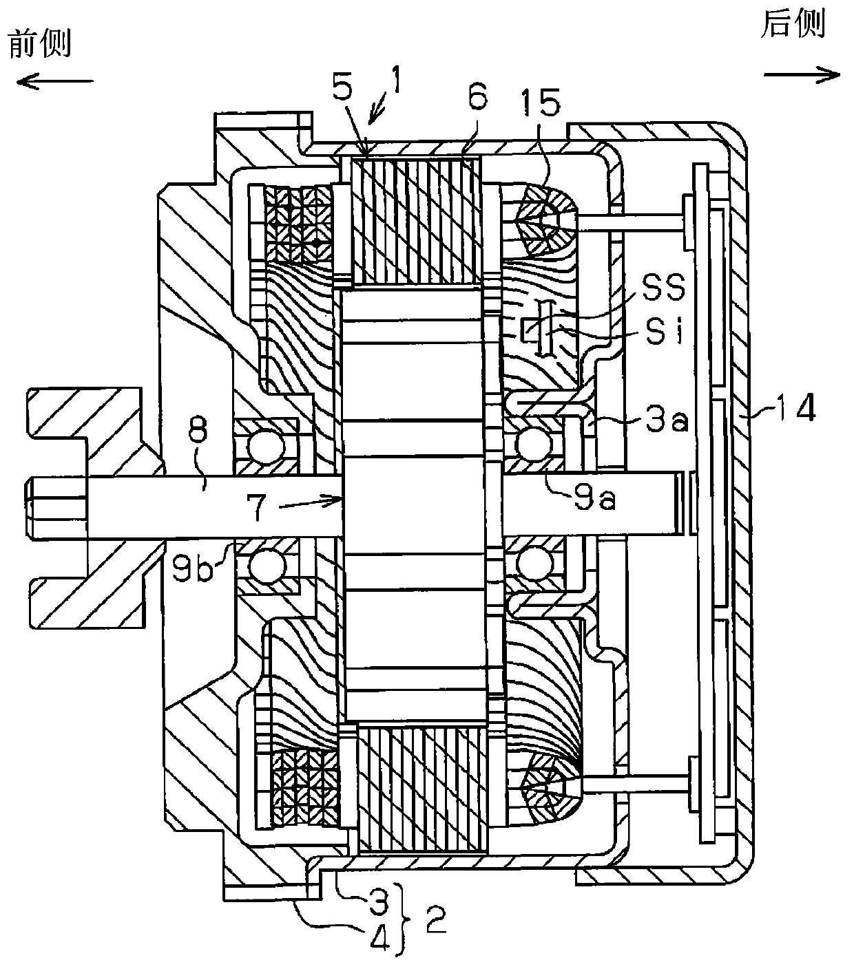
[0071] Such as figure 1 As shown, the motor housing 2 of the motor 1 has: a bottomed cylindrical shell 3; and a front cover 4, the front side of the shell 3, that is, figure 1 The opening on the middle left is closed. The circuit storage box 14 that accommodates power circuits such as circuit boards is installed on the rear side of the casing 3, that is, figure 1 on the middle right end.
[0072] The stator 5 is fixed to the inner peripheral surface of the housing 3 . The stator 5 has: a stator core 6 having a plurality of teeth extending radially inward; and segment conductor (SC) windings 15 wound on the teeth of the stator core 6 . The rotor 7 of the motor 1 has a rotating shaft 8 , and the rotor 7 is arranged inside the stator 5 . The rotary shaft 8 is a non-magnetic metal shaft, and is rotatably supported by a bearing 9 a supported ...
no. 2 Embodiment approach
[0097] The following follows Figure 7 ~ Figure 13 A second embodiment of the present invention will be described.
[0098] Such as Figure 7 As shown, the motor case 2 of the brushless motor 1 has a bottomed cylindrical case 3 and a front cover 4 that closes the front opening of the case 3 . The stator 5 is fixed to the inner peripheral surface of the casing 3 . The stator core 6 of the stator 5 is formed by laminating a plurality of stator core pieces 6 a made of steel plates.
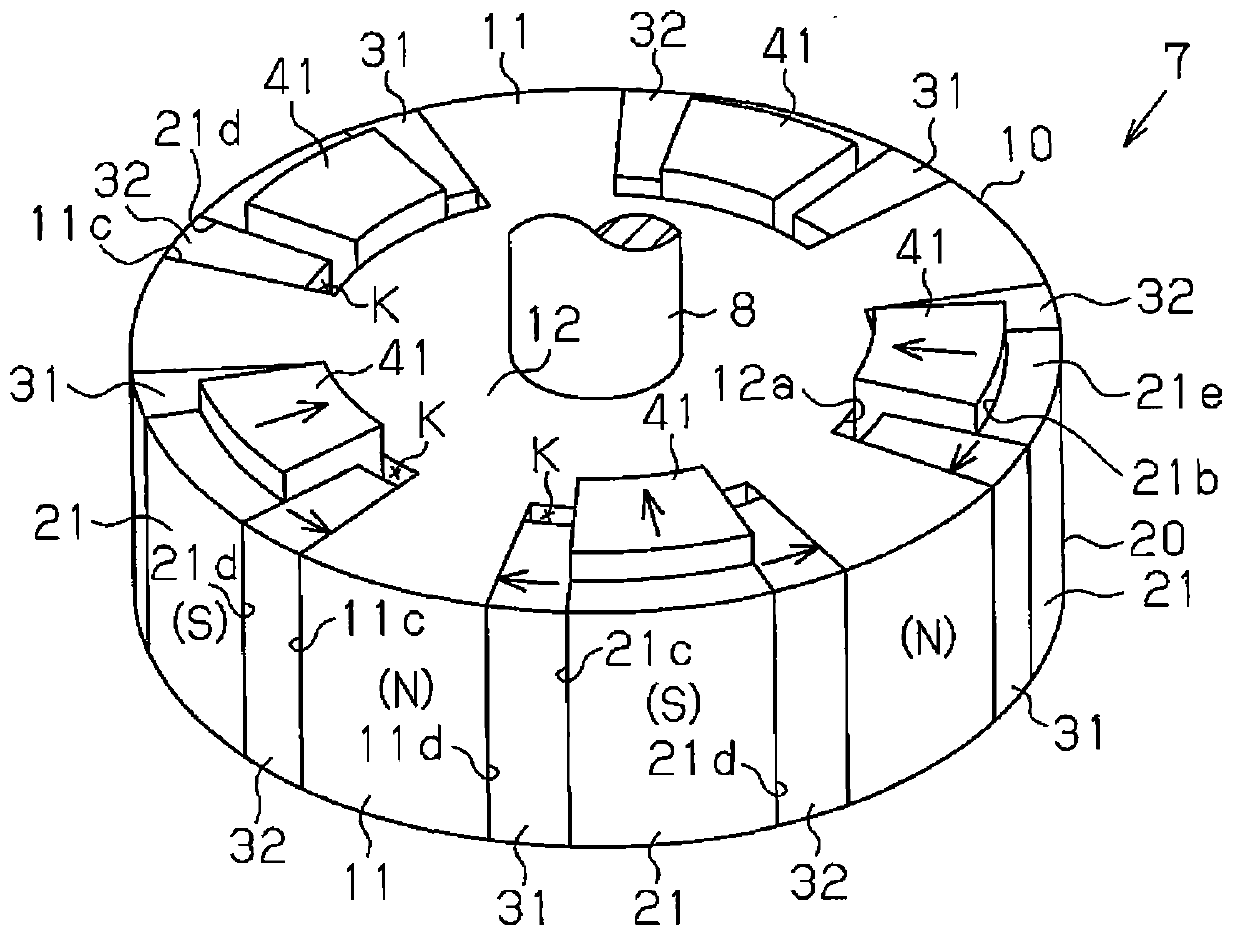
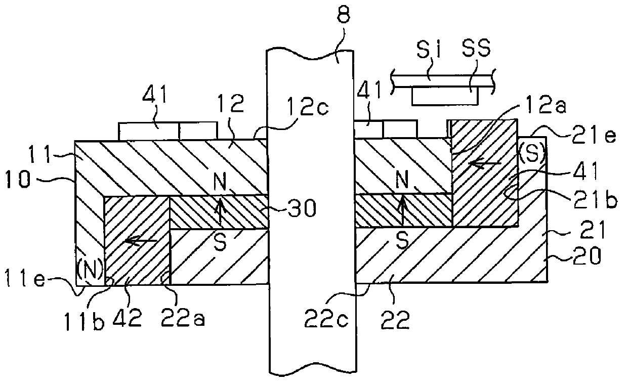
[0099] Such as Figure 7 As shown, the rotor 7 is disposed inside the stator 5 , and the rotor 7 is inserted and fixed by the rotating shaft 8 . In the present embodiment, the rotating shaft 8 is a non-magnetic metal shaft, and is rotatably supported by a bearing 9 a provided on the bottom of the casing 3 and a bearing 9 b provided on the front cover 4 . The rotor 7 fixed on the rotating shaft 8 is a claw pole structure.
[0100] Such as Figure 8 , Figure 9 and Figure 13 As shown, the rot...
no. 3 Embodiment approach
[0145] then follow Figure 14 ~ Figure 17 A third embodiment of the present invention will be described.
[0146] This embodiment is characterized by the anti-scattering structure of the first and second back surface auxiliary magnets 41 and 42 and the first and second interpole magnets 31 and 32 provided on the rotor 7, and other structures are the same as those of the above-mentioned second embodiment. . Therefore, for convenience of description, only characteristic parts will be described in detail, and common parts will be given the same reference numerals and descriptions will be omitted.
[0147] Such as Figure 14 ~ Figure 17 As shown, on the opposite facing surface 12c of the first core base 12, the first fixing plate 61 for preventing scattering is fixed, and the opposite facing surface 22c of the second core base 22 is fixed with a fixing plate 61 for preventing scattering. The second fixing plate 62 . In the present embodiment, the first and second fixing plates...
PUM
 Abstract
Description
Claims
Application Information
 - R&D
- Intellectual Property
- Life Sciences
- Materials
- Tech Scout
- Unparalleled Data Quality
- Higher Quality Content
- 60% Fewer Hallucinations
Browse by: Latest US Patents, China's latest patents, Technical Efficacy Thesaurus, Application Domain, Technology Topic, Popular Technical Reports.
© 2025 PatSnap. All rights reserved.Legal|Privacy policy|Modern Slavery Act Transparency Statement|Sitemap|About US| Contact US: help@patsnap.com