Visible fundus examination tester
A fundus inspection and fuselage technology, applied in the field of medical devices, can solve the problems of inaccurate diagnosis results, no automatic recording and storage function of the inspection instrument, easy to produce visual fatigue, etc., and achieve the effect of reducing the number of components equipped
- Summary
- Abstract
- Description
- Claims
- Application Information
AI Technical Summary
Problems solved by technology
Method used
Image

Examples
Embodiment Construction
[0012] The preferred embodiments of the present invention will be described in detail below in conjunction with the accompanying drawings, so that the advantages and features of the present invention can be more easily understood by those skilled in the art, so as to define the protection scope of the present invention more clearly.
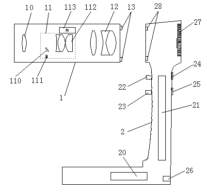
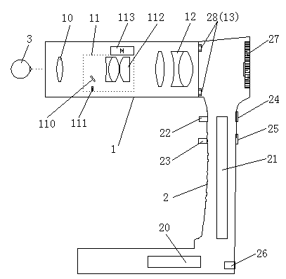
[0013] see figure 1 , the embodiment of the present invention includes: a visual fundus inspection instrument, including: a fundus inspection lens 1 and a body 2, the body 2 is an L-shaped structure, a battery 20 and a control circuit board 21 are arranged inside the body 2, the body 2 is provided with a power switch 22, a shutter button 23, an infrared brightness adjustment button 24 and a focus button 25, a data transmission interface 26 is provided at the rear of the fuselage 2, and a digital camera for infrared reception is provided at the head of the fuselage 2. 27 and the first circuit control line port 28, and the control circuit board 21 ...
PUM
 Abstract
Description
Claims
Application Information