Mixing and stirring tank

A technology of mixing and main stirring, which is applied in mixers, mixers with rotating stirring devices, dissolution, etc. It can solve problems such as unstable product quality, easy stratification of different particles, uneven mixing, etc.

A technology of mixing and main stirring, which is applied in mixers, mixers with rotating stirring devices, dissolution, etc. It can solve problems such as unstable product quality, easy stratification of different particles, uneven mixing, etc.

CN103100333AInactive Publication Date: 2013-05-15YIXING JUNDA SLURRY TECH

Image

  • Mixing and stirring tank
  • Mixing and stirring tank

Examples


Embodiment Construction

[0013] The present invention will be further described below in conjunction with drawings and embodiments.

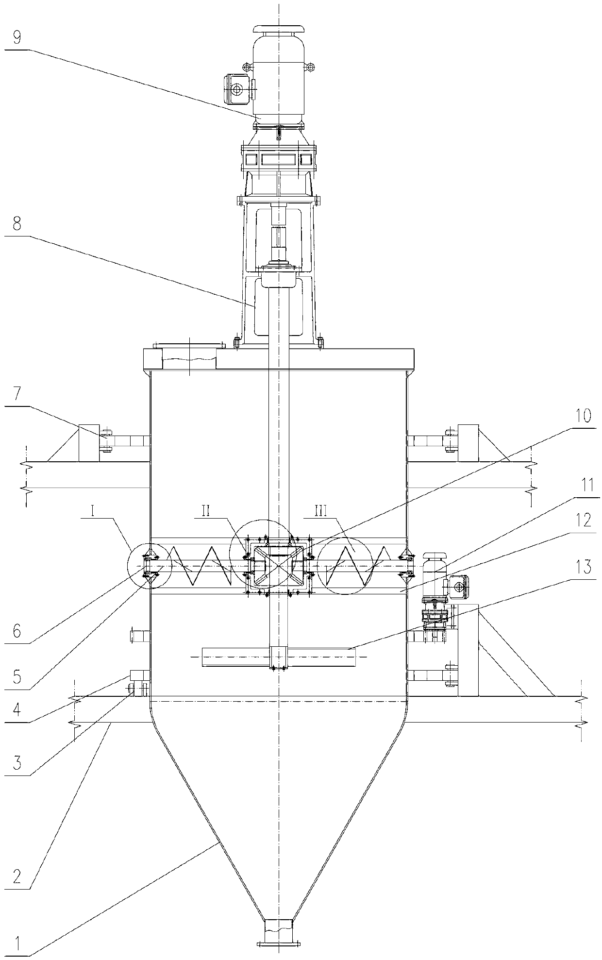
[0014] Such as figure 1 As shown, the device includes a tank body 1, and the tank body 1 includes an upper cylindrical part and a lower cone part. The main body of the tank body 1 is movably connected on the platform 2, on the outside of the tank body 1 is provided with a support wheel set 3 and a roller set 7 which can rotate the tank body 1, and they can be selected or connected with the gear drive group 11 respectively, so that the tank body The body 1 rotates along the periphery of the cylindrical part to enhance the mixing effect.

[0015] The tank body 1 is provided with a vertical main stirring device 8. The main stirring device 8 mainly includes a main shaft and a blade, wherein the blade adopts a hinged agitator 13, which is located in the tank body 1, and the upper end of the main shaft is connected to the outside of the tank body 1. The stirring motor 9. O...


PUM


Abstract

The invention discloses a mixing and stirring tank which comprises a tank body, a main vertical stirring device and a stirring motor, wherein a stirring blade at the lower end of the main stirring device is positioned in the tank body; the other end of the main stirring device is connected with the stirring motor outside the tank body; one or more transverse auxiliary stirrers are arranged in the tank body; and one ends of the auxiliary stirrers are connected with a spindle of the main stirring device trough a gear, and the other ends of the auxiliary stirrers are connected to the tank body through a bearing. According to the device, materials can be rotated and mixed in the tank body in the horizontal direction and can be further turned and mixed up and down, so that the materials are stirred more fully and completely, and the mixing effect is obviously improved.

Description

technical field [0001] The invention belongs to the field of stirring tanks, in particular to a mixing tank. Background technique [0002] The existing mixing tanks are generally only equipped with vertical mixing blades in the axial direction. This kind of mixing method that makes the materials rotate in one direction for mixing or stirring will lead to uneven mixing and different particles in some fields that have high requirements for mixing. According to the different specific gravity, it is easy to stratify, and the product quality is unstable. Contents of the invention [0003] The object of the present invention is to provide a mixing and stirring tank in order to overcome the above defects. [0004] The purpose of the present invention can be achieved through the following measures: [0005] A mixing and stirring tank, comprising a tank body, a main stirring device and a stirring motor, the main stirring device is arranged vertically, the stirring blade at the lo...

Claims


Application Information

Patent Timeline
15 May 2013
Publication
CN103100333A
IPC
B01F7/18; B01F7/08
Inventors
刘定国; 丁奎刚