

Foaming machine
A technology of foaming machine and driving mechanism, which is applied in mixers, mixers with rotating containers, mixing methods, etc. It can solve the problems of single stirring form, swirl and stratification of raw materials, etc., and achieve high stirring efficiency and high foaming speed. Fast, avoid swirl and layered effects
- Summary
- Abstract
- Description
- Claims
- Application Information
AI Technical Summary
Problems solved by technology
Method used
Image

Examples
specific Embodiment approach 1
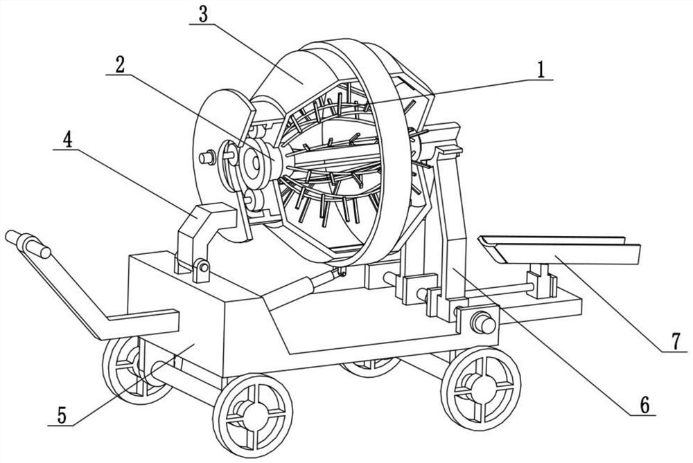
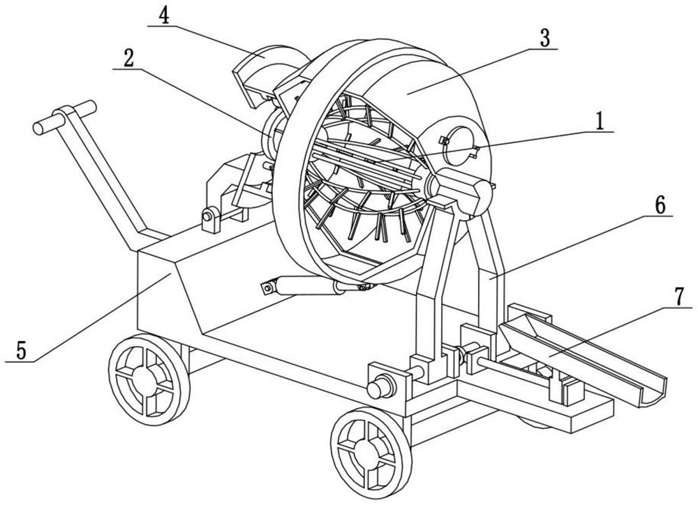
[0027] Combine below Figure 1-10 Describe this embodiment, the present invention relates to the field of foaming machine technology, more specifically, a foaming machine, including an elastic adjustment foaming mechanism 1, an adjustment drive mechanism 2, a foaming rotating tank mechanism 3, and a rotating power mechanism 4 , the loading and unloading rotating mechanism 5, the tank supporting mechanism 6 and the discharge guiding mechanism 7, the tank supporting mechanism 6 is fixedly connected to the loading and unloading rotating mechanism 5, and the discharging guiding mechanism 7 is fixedly connected to the right end of the loading and unloading rotating mechanism 5 , the tank supporting mechanism 6 and the tank supporting mechanism 6 are meshed for transmission, the rotating power mechanism 4 is rotatably connected to the loading and unloading rotating mechanism 5, the foaming rotating tank mechanism 3 is rotatably connected to the rotating power mechanism 4, and the adj...
specific Embodiment approach 2
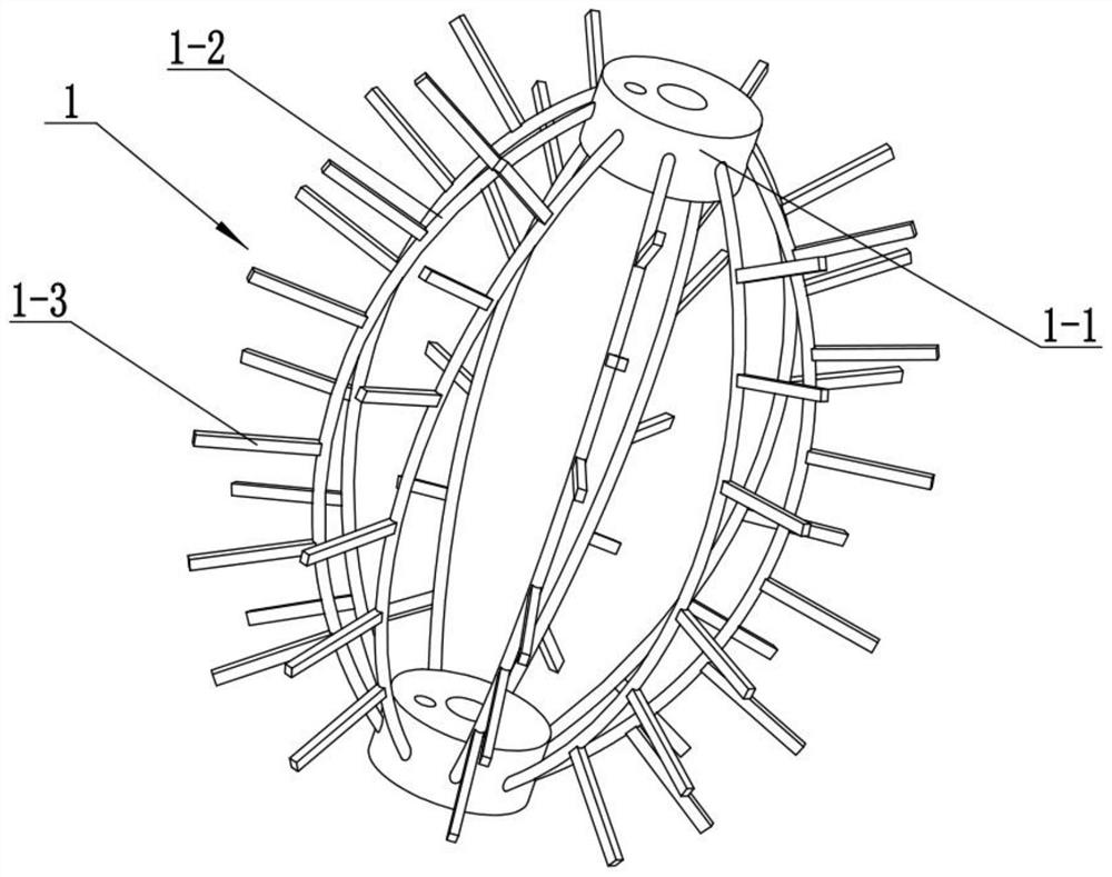
[0030] Combine below Figure 1-10 Describe this embodiment, this embodiment will further explain the first embodiment, the elastic adjustment and foaming mechanism 1 includes an opening and closing adjustment bushing 1-1, an arc-shaped elastic connecting rod 1-2 and a foaming stirring rod 1-3 , there are two opening and closing adjustment bushings 1-1, and a plurality of arc-shaped elastic connecting rods 1-2 are arranged between the two opening-closing adjusting bushings 1-1, and a plurality of arc-shaped elastic connecting rods 1-2 All are provided with a plurality of foaming stirring rods 1-3.
[0031] When the two opening and closing adjustment bushings 1-1 are close to each other, the two opening and closing adjustment bushings 1-1 will squeeze a plurality of arc-shaped elastic connecting rods 1-2, so that the plurality of arc-shaped elastic connecting rods 1-2 Bending occurs, and at the same time, multiple arc-shaped elastic connecting rods 1-2 drive multiple foaming st...
specific Embodiment approach 3
[0033] Combine below Figure 1-10 Describe this embodiment, this embodiment will further explain the second embodiment, the adjustment drive mechanism 2 includes a follow-up rotating cylinder 2-1, a connecting plate 2-2, a rotating screw rod 2-3, and a limit slide rod 2 -4, adjust the motor 2-5 and the ring rack 2-6, the ring rack 2-6 is fixedly connected to the left end of the follow-up rotating cylinder 2-1, and the rotating screw mandrel 2-3 is connected to the follow-up rotating cylinder 2-1 in rotation And on the connecting plate 2-2, the rotating screw mandrel 2-3 is fixedly connected on the output shaft of the adjustment motor 2-5, the adjustment motor 2-5 is fixedly connected in the follow-up rotating cylinder 2-1, and the limit slide bar 2- 4. It is fixedly connected to the follow-up rotating cylinder 2-1 and the connecting plate 2-2. The two opening and closing adjustment bushings 1-1 are connected to the left and right sides of the rotating screw rod 2-3 through thr...
PUM
 Abstract
Description
Claims
Application Information