

Drive-in tool
A technology for driving into tools and top covers, which is applied in the direction of nailing tools, manufacturing tools, portable motorized devices, etc. It can solve problems such as gas leakage, deformation of exhaust hoods, noise, etc., and achieve high sealing performance and prevent gas leakage.
- Summary
- Abstract
- Description
- Claims
- Application Information
AI Technical Summary
Problems solved by technology
Method used
Image

Examples
Embodiment Construction
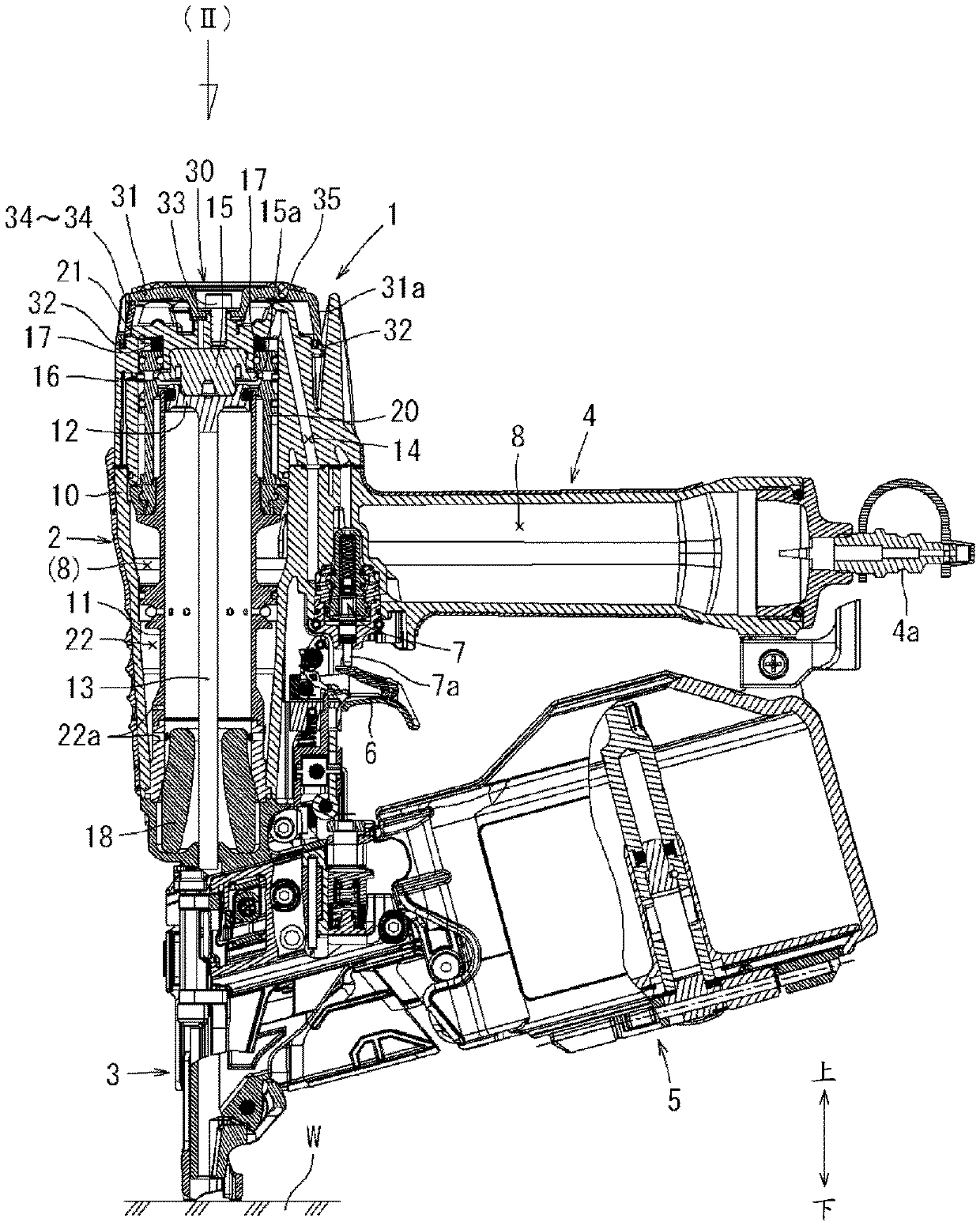
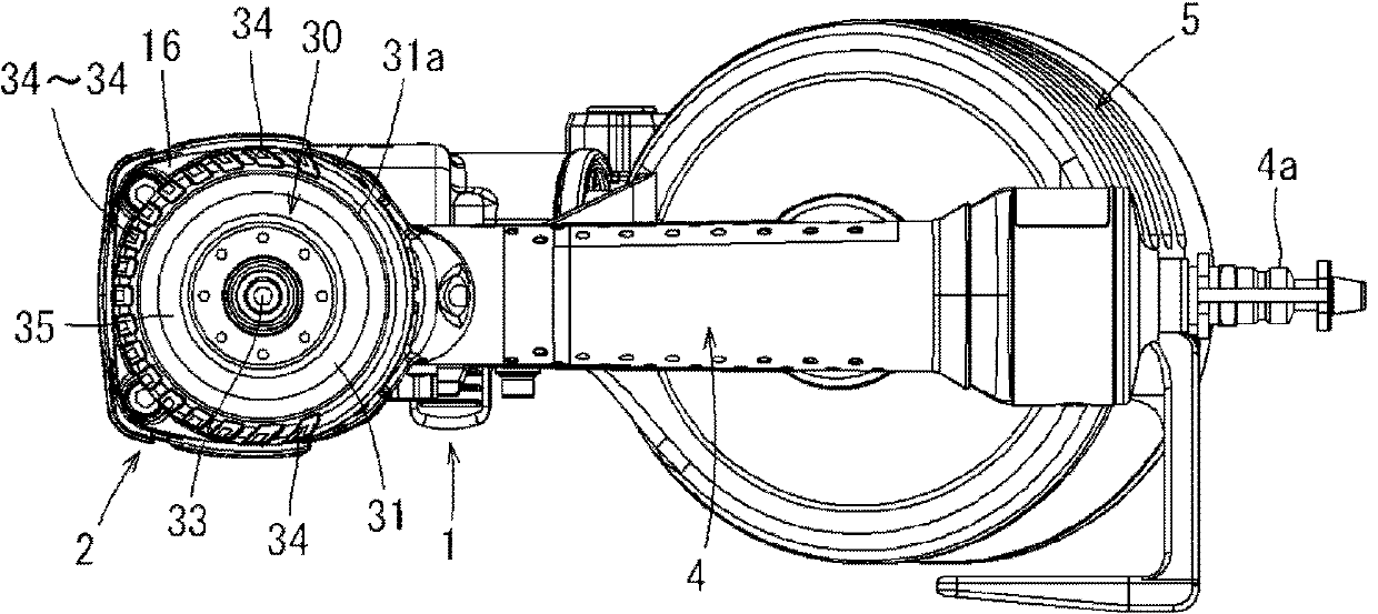
[0028] Second, based on Figure 1 to Figure 5 Embodiments of the present invention will be described. figure 1 The driving tool 1 according to this embodiment is shown in . This driving tool 1 is a nail driver using compressed air as a driving source, and includes a main body 2 , a driving unit 3 , a handle 4 , and a magazine 5 .
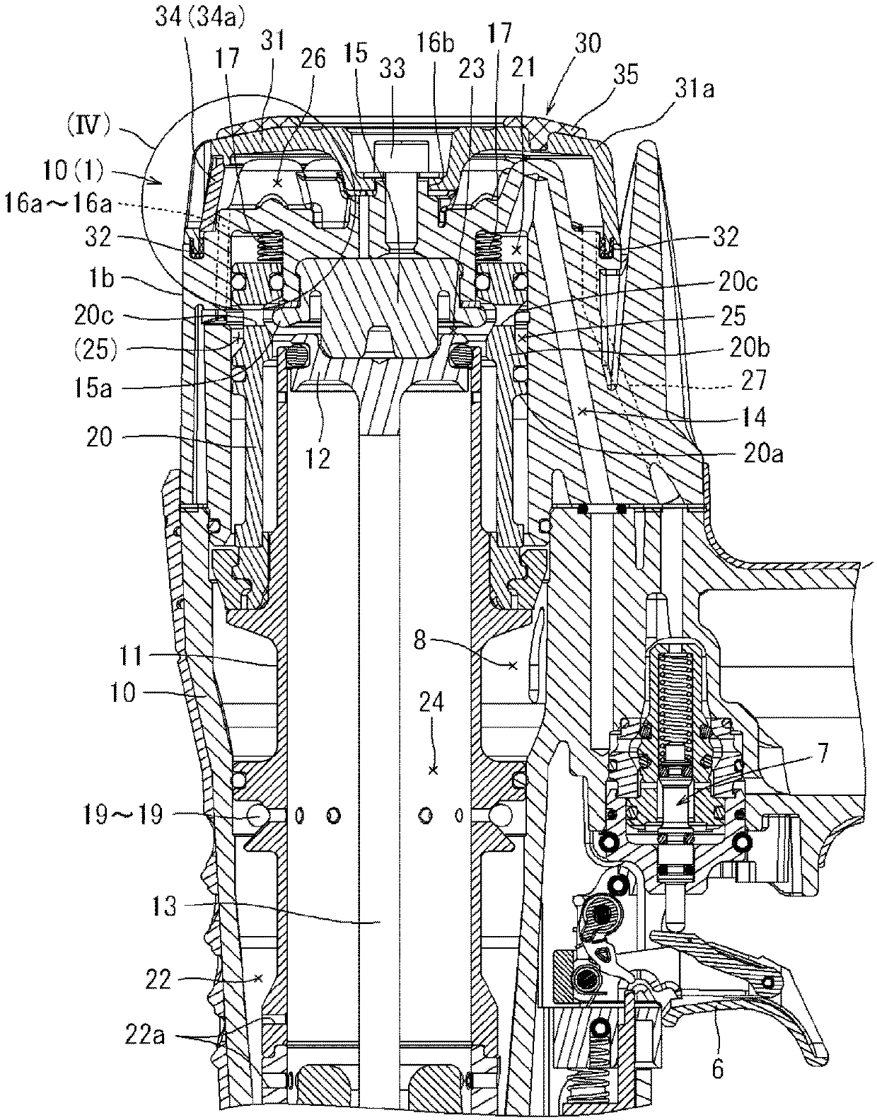
[0029] A cylindrical cylinder 11 and a piston 12 that reciprocates in the cylinder 11 by compressed gas are installed in the main body 2 . The cylinder block 11 is housed so as to straddle the interior of the cylindrical main body case 10 and the interior of the magnesium top cover 16 joined to the upper part of the main body case 10 . At the center of the lower surface of the piston 12, a driver 13 for striking the driving part is installed. The driver 13 extends downward in the cylinder 11 , and its front end reaches the driving portion 3 .
[0030] Such as image 3 As shown, a cylindrical overhead valve 20 is built in around the upper side o...
PUM
 Abstract
Description
Claims
Application Information