Supercharge Your Innovation With Domain-Expert AI Agents!

Motor vehicle body with expandable element

A technology for expanding parts and bodies, applied in vehicle parts, vehicle safety arrangements, pedestrian/occupant safety arrangements, etc.

Active Publication Date: 2013-05-15
GM GLOBAL TECH OPERATIONS LLC
View PDF6 Cites 1 Cited by
  • Summary
  • Abstract
  • Description
  • Claims
  • Application Information

AI Technical Summary

Problems solved by technology

This requirement is difficult to meet with the conventional structures mentioned above, because not only the expandable part, but also the connecting part (which will prevent the cover plate from being thrown forward due to the expansion of the expandable part) must be located inside the tank space, and the cover plate must be located inside the tank space. The edges of the slot stick out on both sides

Method used


Image

  • Motor vehicle body with expandable element
  • Motor vehicle body with expandable element
  • Motor vehicle body with expandable element

Examples


Embodiment Construction

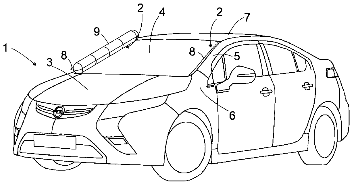
[0023] figure 1 A perspective view of a motor vehicle 1 is shown with a windshield 4 delimited laterally by A-pillars 2 and lowerly by a bonnet 3 . From the observer's point of view, the A-pillar on the right shows the normal state, the exposed section 5 of the outer wall of the A-pillar 2 transitions downwards to the front fender 6 and upwards to the roof panel 7 . The elastic cover 8 extends between the bare section 5 and the windshield 4 . In the interior of the A-pillar 2, in the lower part of the cover plate 8, an inflatable part is concealed, for example in the form of a rubber hose, which is connected to a gas generator, in particular a smoke burst generator, for the purpose of produce swelling.

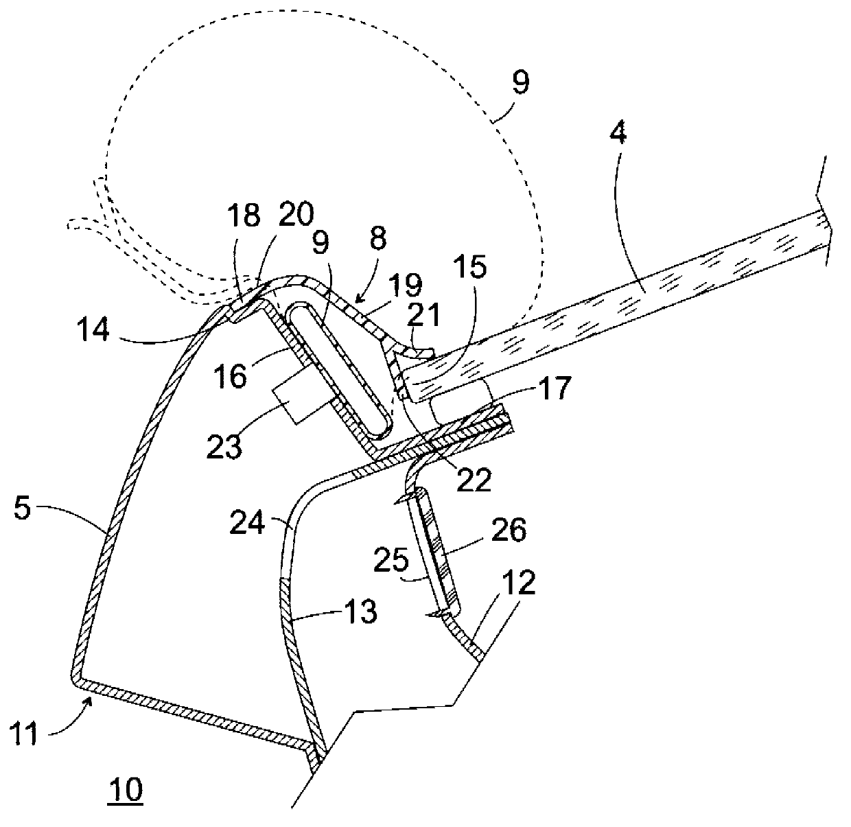
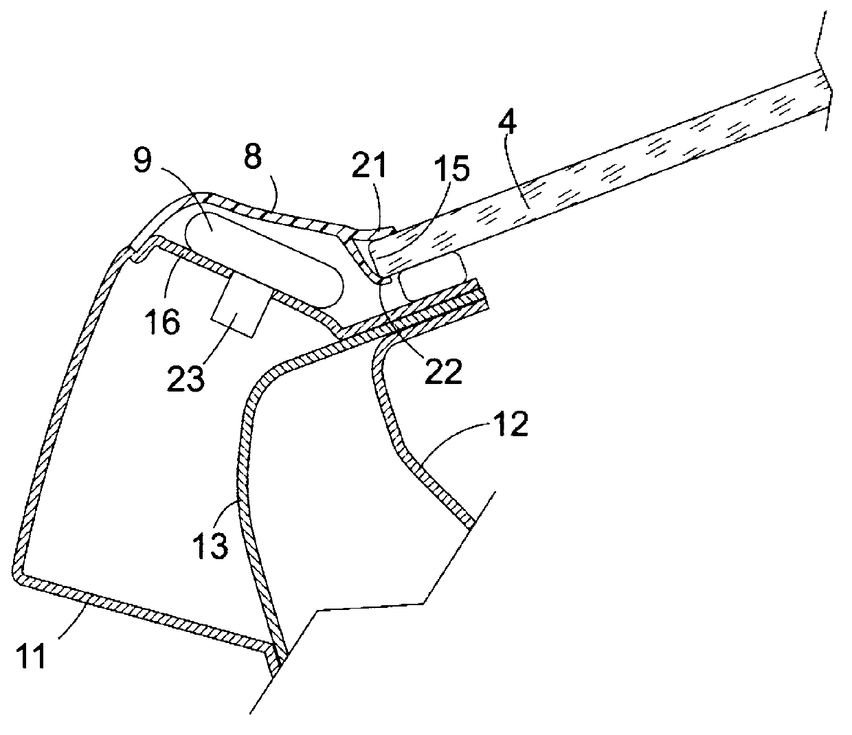
[0024] Shown on the A-pillar 2 on the left, from the viewer's perspective, is the inflatable member (here referenced 9 ) in an inflated state. During the expansion of the expandable part 9 , it presses the cover panel 8 sideways, in which case it extends substantially cylin...


PUM


Abstract

A body for a motor vehicle (1) that comprises a windshield (4), and an A-column (2) at both sides of the windshield (4), at least one expandable element(9, 30) arranged on the an A-column (2) along the edge(15) of the windshield (4), and a cover plate that covers an installation space of the at least one expandable element(9, 30) and tightly adjoins the windshield (4).

Description

technical field [0001] The invention relates to a vehicle body with an inflatable part in the event of an accident in order to cushion the impact of a pedestrian with the vehicle body as much as possible. Background technique [0002] It is known from DE 103 53 447 A1 to design the A-pillar of a motor vehicle body as a shell-shaped longitudinal profile closed by a movable cover, in which an expandable element is accommodated in the interior cavity of the longitudinal profile. As a result of the expansion of this expandable part in the event of an accident, the cover of the A-pillar is pressed forwards in order to possibly block and delay the head of a pedestrian before it reaches the A-pillar. [0003] To avoid unnecessarily restricting the driver's visibility, the car's A-pillars should be as slim as possible. This requirement is difficult to meet with the conventional structures mentioned above, because not only the expandable part, but also the connecting part (which wil...

Claims


Application Information

Patent Timeline
Patent Type & Authority Applications(China)
IPC IPC(8): B60R21/36
CPCB60R21/36
Inventor U.里克
Owner GM GLOBAL TECH OPERATIONS LLC
Features
  • R&D
  • Intellectual Property
  • Life Sciences
  • Materials
  • Tech Scout
  • Unparalleled Data Quality
  • Higher Quality Content
  • 60% Fewer Hallucinations
Learn More