Hydraulic crane of underground transfer rail

A hydraulic and crane technology, used in cranes and other directions, can solve the problems of small working range, large car body size, and not very wide working track.

Inactive Publication Date: 2013-05-15
LIAONING XINFENG MINE IND GRP CO LTD
View PDF9 Cites 8 Cited by
  • Summary
  • Abstract
  • Description
  • Claims
  • Application Information

AI Technical Summary

Problems solved by technology

[0005] 1. There are only longitudinal working wheels along the front and rear directions of the frame on the flat frame, and there are no horizontal working wheels along the left and right directions of the frame, so it is difficult to move laterally and the working range is small. Walking mobile wheels, when the underground track-changing hydraulic crane needs to move in the roadway, it can only be placed on the flatbed truck to move in the coal mine underground roadway;
[0006] 2. The downward hydraulic telescopic arm connected with the working wheels is positioned and connected to the side of the flat frame, the working track is not very wide, and the stability of the lifting operation is not very high;
[0007] 3. The roof hydraulic cylinder stands vertically above the rear of the longitudinal beam. Because the roof hydraulic cylinder is longer, the car body is larger and it is inconvenient for the underground rail changing hydraulic crane to move in the roadway.

Method used


Image

  • Hydraulic crane of underground transfer rail
  • Hydraulic crane of underground transfer rail
  • Hydraulic crane of underground transfer rail

Examples


Embodiment Construction

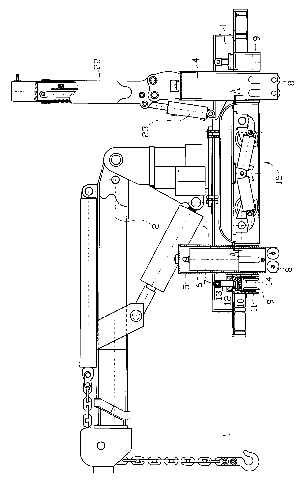
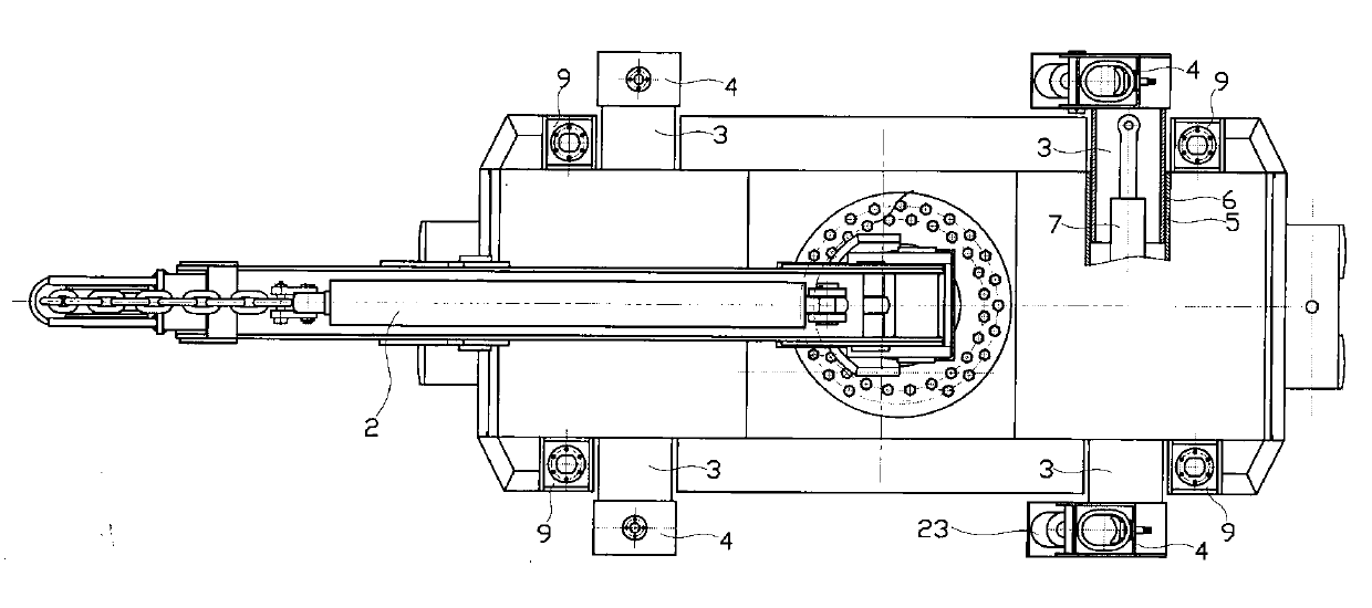
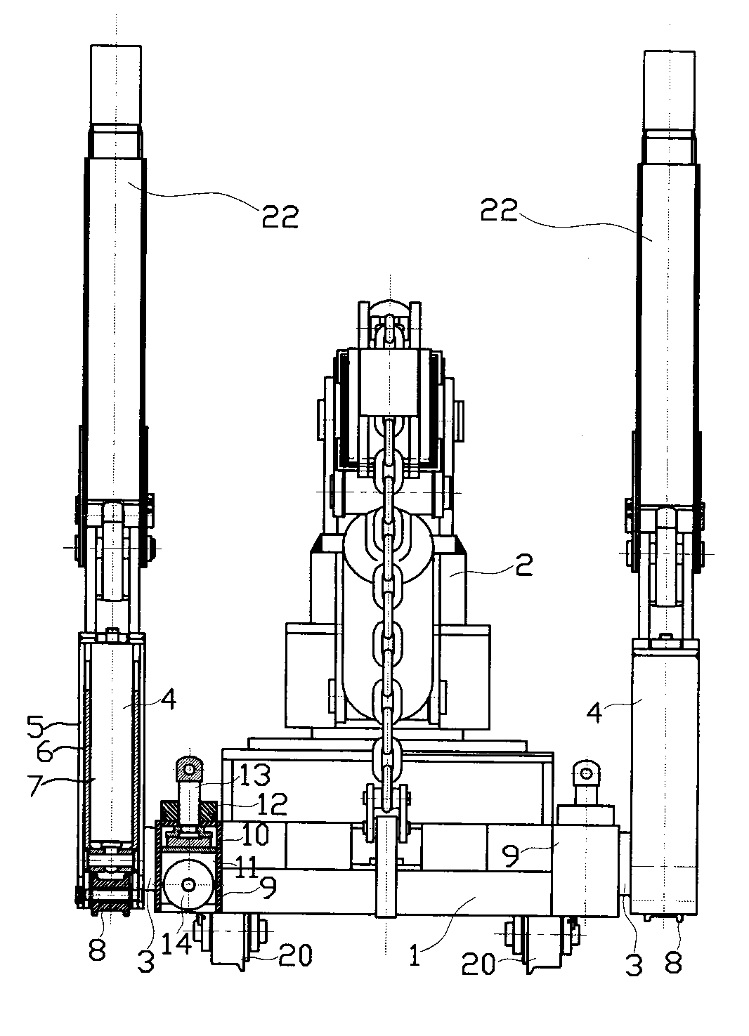
[0022] Figure 1~Figure 5 Among them, the underground track-changing hydraulic crane has a rectangular flat frame 1, a hydraulic lifting frame 2 is arranged in the middle above the flat frame, and the front and rear parts of the left and right sides of the flat frame are respectively connected with lateral hydraulic telescopic arms 3. The outer end of the hydraulic telescopic arm is connected with the downward hydraulic telescopic arm 4 perpendicular to the vehicle frame plate, and the lateral hydraulic telescopic arm and the downward hydraulic telescopic arm have a fixed square tube 5 and a sliding square tube that can slide in the fixed square tube 6. A hydraulic cylinder 7 is connected between the fixed square cylinder and the sliding square cylinder. The lower end of the downward hydraulic telescopic arm is connected with a longitudinal working wheel 8. The four corners of the flat frame are respectively connected with a downward screw driving the telescopic arm 9. The dri...


PUM


Abstract

The invention discloses a hydraulic crane of an underground transfer rail. A hydraulic lifting rack is arranged in the middle of a plate frame; lateral hydraulic telescopic booms are respectively connected with the front part and the rear part of the left side and the right side of the frame; downward hydraulic telescopic booms are arranged at the outer ends of the lateral hydraulic telescopic booms; longitudinal operation wheels are connected to the lower ends; downward screw driving telescopic booms are arranged at four corners of the frame; the lower ends of the frame are connected with transverse operation wheels; longitudinal moving wheels driven by a hydraulic lever lifting mechanism are arranged below the frame; the upper ends of the downward hydraulic telescopic booms at the left and right rear parts are connected with supporting hydraulic cylinders; and the supporting hydraulic cylinders are connected with a swing hydraulic cylinder. The hydraulic crane of the underground transfer rail comprises operation wheels in the length direction and the operation wheels in the width direction, is large in operation range and high in stability of lifting operation, also comprises moving wheels, and can move on a flat car track for rail transferring without a flat car in a coal mine roadway; the swing hydraulic cylinder can enable the supporting hydraulic cylinder to be parallel to the plate frame; the hydraulic crane of the underground transfer rail is small in size and convenient to move in a narrow roadway.

Description

technical field [0001] The invention relates to a hydraulic crane used in the installation and withdrawal of a complete set of underground fully-mechanized mining equipment in a coal mine, in particular to a wheel of the hydraulic crane used in the installation and withdrawal of a complete set of underground fully-mechanized mining equipment in a coal mine. Background technique [0002] When installing and withdrawing the complete set of fully mechanized mining equipment in the coal mine, many equipment need to be hoisted or moved a short distance in the hoisted state during the installation and withdrawal process. The operation of this kind of hoisting equipment on the ground can be easily completed with a common hydraulic crane on the ground because the environment is spacious. The general hydraulic crane on the ground has a rectangular vehicle frame, the top of the vehicle frame has a hydraulic lifting frame, and the bottom of the vehicle frame is connected with longitudi...

Claims


Application Information

Patent Timeline
Patent Type & Authority Applications(China)
IPC IPC(8): B66C23/36B66C23/62
Inventor 张希望
Owner LIAONING XINFENG MINE IND GRP CO LTD
Why Eureka
Try Eureka