
Hybrid power filter main circuit

A hybrid power and filter circuit technology, applied to harmonic reduction devices and AC networks to reduce harmonics/ripples, etc., can solve the problem of not having the function of compensating fundamental reactive power and filtering characteristic sub-harmonic currents, system filtering Problems such as limited harmonic capacity and reduced compensation accuracy can achieve the effects of improving overall economy, reducing cost and volume, and improving accuracy

Inactive Publication Date: 2013-05-15
HUNAN LINENG TECH +1
View PDF2 Cites 10 Cited by
  • Summary
  • Abstract
  • Description
  • Claims
  • Application Information

AI Technical Summary

Problems solved by technology

Its disadvantages are: the active filter has to withstand the fundamental voltage, which is not suitable for high-voltage systems; it does not have the function of compensating the fundamental reactive power and filtering the characteristic sub-harmonic current of the passive filter, and the capacity of the system to filter harmonics is limited. limit
In order to ensure that the low-voltage active part can filter out the high-voltage harmonic current, the existing hybrid power filter uses a coupling transformer to connect the active filter and the passive filter, but this will lead to a decrease in the overall system economy and an increase in volume. Large, and the compensation current will cause phase delay through the coupling transformer, and the compensation accuracy will decrease

Method used


Image

  • Hybrid power filter main circuit
  • Hybrid power filter main circuit
  • Hybrid power filter main circuit

Examples


Embodiment Construction

[0020] The present invention will be further described below in conjunction with accompanying drawing.

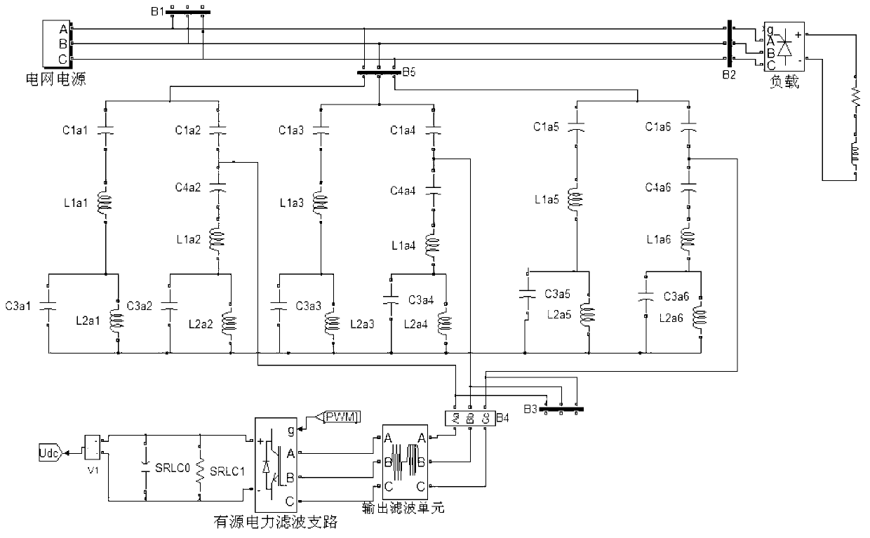
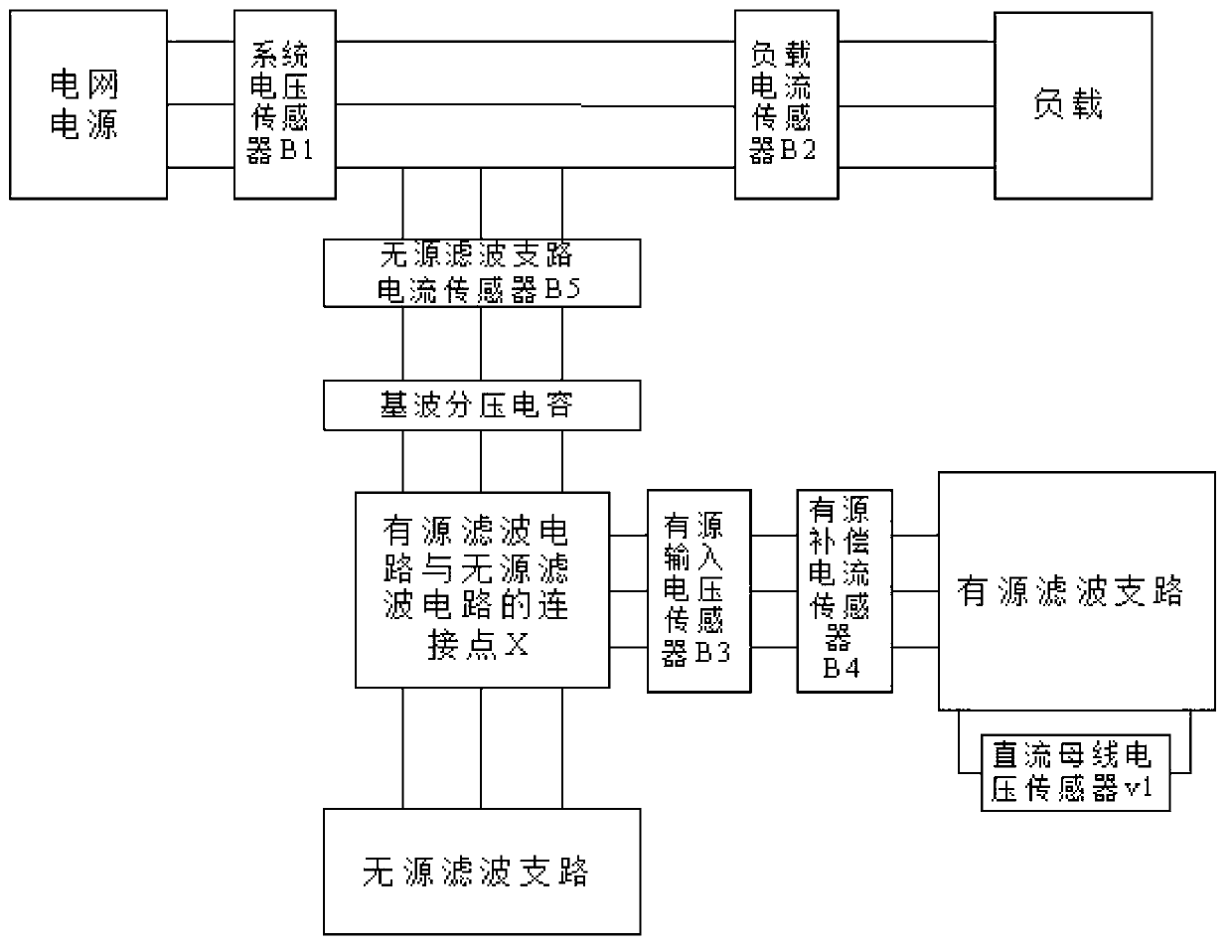
[0021] The invention includes a passive filter circuit, an active filter circuit and a measurement circuit. The passive filter circuit includes a double-tuned filter branch and a fundamental wave divided voltage series double-tuned filter branch. The two branches are connected in parallel. The grid power supply is connected to the passive filter circuit, and the passive filter circuit is connected to the active filter circuit. The connection point is at the capacitive voltage divider point of the fundamental wave voltage division series double-tuned filter branch in the passive filter circuit.

[0022] The distribution principle of harmonic filtering in the present invention is that the passive filter circuit is responsible for low-order harmonics (3, 5, and 7th), and the active filter circuit is responsible for filtering of 11th and above high-order harmonics. The purpose ...


PUM


Abstract

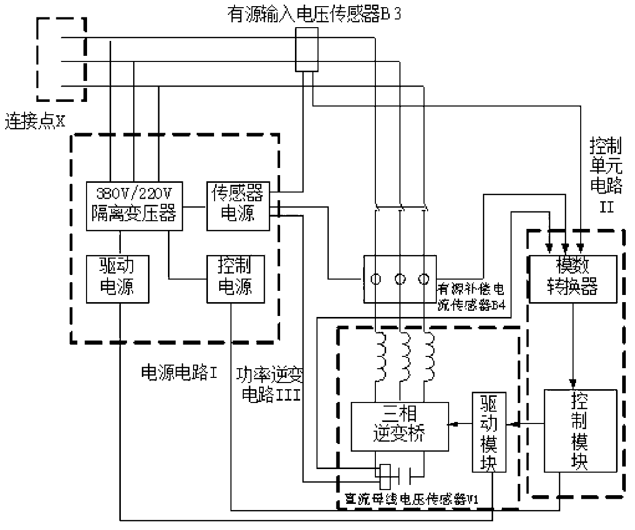
The invention discloses a hybrid power filter main circuit which comprises a passive filter circuit, an active filter circuit and a measuring circuit, wherein the passive filter circuit consists of a double-tuned filter branch circuit and a base-wave partial-pressure series double-tuned filter branch circuit; a resonance point of one double-tuned filter branch circuit is set to be three times or five times, and a resonance point of the other branch circuit is set to be five times or seven times; the passive filter circuit is directly connected with the active filter circuit by a circuit instead of a coupling transformer; and the measuring circuit comprises a voltage sensor B1 at a power grid side, a load current sensor B2 at the power grid side, a passive filter branch circuit current sensor B5 in a passive filter branch circuit, a voltage sensor B5 at an active and passive connecting point, a compensating current sensor B4 in the active filter circuit, and a direct current (DC) bus voltage sensor V1. Due to the structure without the coupling transformer, the cost and the size of a system are obviously reduced, the defect of compensating current phase delay caused by the coupling transformer can be overcome, and the compensation precision is improved.

Description

technical field [0001] The invention relates to a power filter, in particular to a main circuit of a hybrid power filter. Background technique [0002] At present, the existing hybrid power filter includes a filter branch composed of an active filter and a passive filter in series, and is equipped with a current detector and a compensation current detector for grid current detection; A hybrid power filter composed of a fundamental wave series resonant passive filter connected in parallel, and the active filter and the passive filter are coupled through an isolation transformer. Its disadvantages are: the active filter has to withstand the fundamental voltage, which is not suitable for high-voltage systems; it does not have the function of compensating the fundamental reactive power and filtering the characteristic sub-harmonic current of the passive filter, and the capacity of the system to filter harmonics is limited. limit. In order to ensure that the low-voltage active ...

Claims


Application Information

Patent Timeline
IPC IPC(8): H02J3/01
CPCY02E40/40
Inventor 陈岗刘泉邓名高关维德颜成雄
Owner HUNAN LINENG TECH
Learn More