Loading equipment

A technology for loading equipment and sets, which is applied in transportation and packaging, conveyor objects, stacking of objects, etc., can solve problems such as low efficiency, high cost, and easily damaged blades, so as to reduce costs, ensure quality, and improve operational efficiency. Effect

Active Publication Date: 2013-05-22
SHENZHEN SHENLAN PRECISION MACHINERY
View PDF6 Cites 40 Cited by
  • Summary
  • Abstract
  • Description
  • Claims
  • Application Information

AI Technical Summary

Problems solved by technology

[0004] The purpose of the present invention is to provide loading equipment, which aims to solve the problems of low efficiency, high cost and easy damage to the blade due to the manual operation of placing the blade and the gasket on the jig in the prior art

Method used


Image

  • Loading equipment
  • Loading equipment
  • Loading equipment

Examples


Embodiment Construction

[0025] In order to make the object, technical solution and advantages of the present invention clearer, the present invention will be further described in detail below in conjunction with the accompanying drawings and embodiments. It should be understood that the specific embodiments described here are only used to explain the present invention, not to limit the present invention.

[0026] The implementation of the present invention will be described in detail below in conjunction with specific drawings.

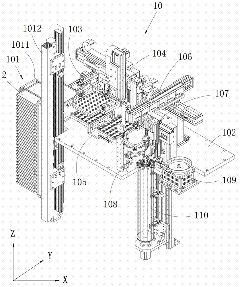
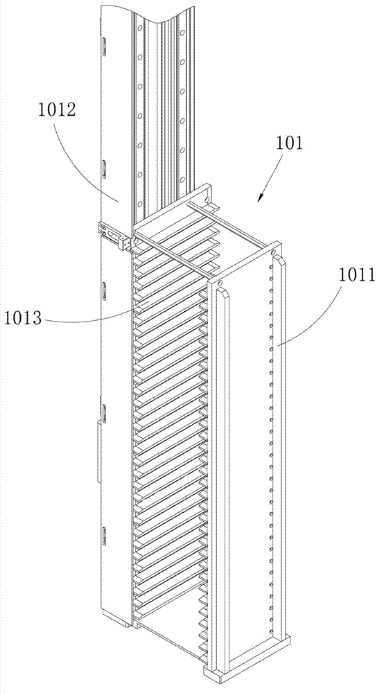
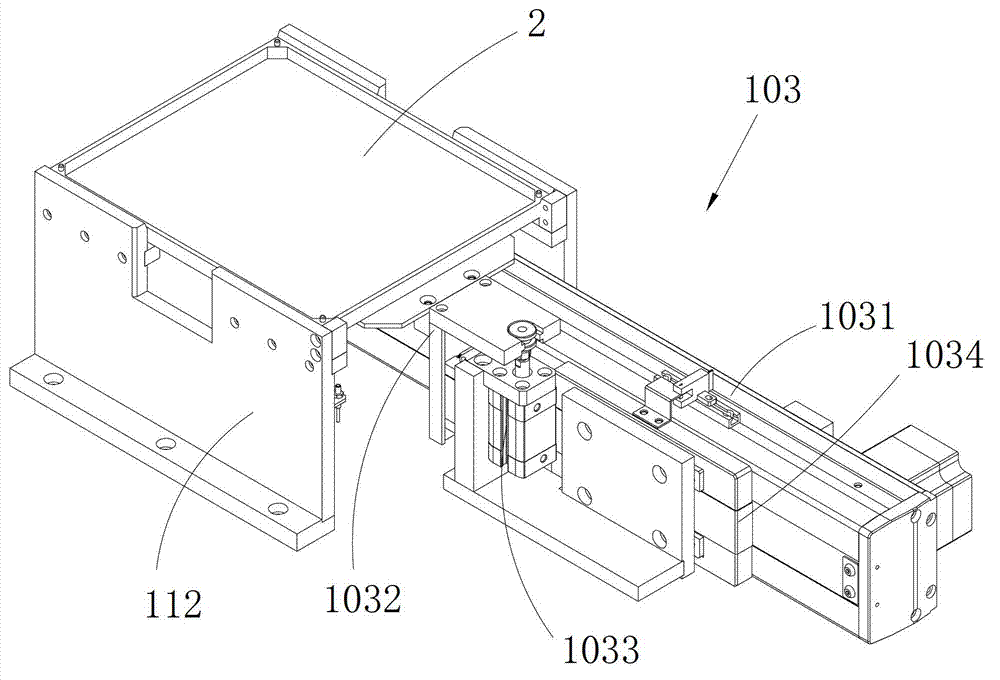
[0027] Such as Figure 1~10 Shown is a preferred embodiment provided by the present invention.

[0028] The loading device 10 provided by the present invention is used to install the blade and the spacer on the jig, and the blade is provided with a central hole, which collects the blade and the spacer on the jig before the blade is coated. definition figure 1 The X direction is the horizontal direction, the Y direction is the vertical direction, and the Z direction is the...


PUM


Abstract

The invention relates to the technical field of mechanical equipment and discloses loading equipment. The loading equipment comprises a charging tray mechanism, a tray moving mechanism, a middle transition mechanism, a turning conveying mechanism, a first part taking mechanism, a rotary platform, a second part taking mechanism and a sleeved mechanism. The charging tray mechanism is used for placing a charging tray, the tray moving mechanism is used for taking out of the charging tray in the charging tray mechanism, the middle transition mechanism is used for placing the charging tray, the turning conveying mechanism is used for grabbing a material plate in the middle transition mechanism, enabling the material plate and the charging tray to be overlapped, and enabling the overlapped material plate and charging tray turning to be arranged on the middle transition mechanism, and the first part taking mechanism and the rotary platform are used for grabbing blades on the charging tray. The second part taking mechanism is used for grabbing blades on the rotary platform and gaskets in a vibration platform, and the sleeved mechanism is used for being sleeved on the blades and the gaskets which are grabbed by the second part taking mechanism. The whole operation process of sleeved equipment is controlled by a control center, achieves automatic operation, does not need manual participation, greatly improves operation efficiency, does not need staff cost, reduces cost, avoids misoperation phenomenon of operation of staff due to adopting of automatic operation, and therefore guarantees quality of the blades.

Description

technical field [0001] The invention relates to the technical field of mechanical equipment, in particular to loading equipment. Background technique [0002] The loading device is a device that widely places blades and gaskets on the jig. The blade is generally a CNC blade with a center hole, and the jig is a PVD coating jig. Of course, it can also be other types. Blades and Jigs. It is used to agglomerate bulk material prior to blade coating. [0003] In the prior art, manual operation is used to place the blade and gasket on the jig. In this way, the efficiency is low, more operators are needed, and the cost is greatly increased, and the blade is easily damaged during the manual operation. , so that the accuracy of the blade is greatly reduced. Contents of the invention [0004] The purpose of the present invention is to provide a loading device, which aims to solve the problems of low efficiency, high cost and easy damage to the blades caused by manually placing the...

Claims


Application Information

Patent Timeline
Patent Type & Authority Applications(China)
IPC IPC(8): B65G47/74B65G47/90B65G57/03B65G61/00
Inventor 郑青焕
Owner SHENZHEN SHENLAN PRECISION MACHINERY
Why Eureka
Try Eureka