
Bearing arrangement for a crankshaft of an internal combustion engine

An internal combustion engine, sliding bearing technology, applied in crankshaft bearings, shafts and bearings, engine components, etc., can solve problems such as limiting the service life of crankshaft bearings

Active Publication Date: 2013-05-22
MAN ENERGY SOLUTIONS SA
View PDF11 Cites 7 Cited by
  • Summary
  • Abstract
  • Description
  • Claims
  • Application Information

AI Technical Summary

Problems solved by technology

Since there is a direct relationship between the bearing temperature and the service life of the bearing material, the local peak temperature essentially in the axial bearing center of the plain bearing limits the service life of the entire crankshaft bearing

Method used


Image

  • Bearing arrangement for a crankshaft of an internal combustion engine
  • Bearing arrangement for a crankshaft of an internal combustion engine
  • Bearing arrangement for a crankshaft of an internal combustion engine

Examples


Embodiment Construction

[0012] The invention here relates to a crankshaft bearing of a crankshaft of an internal combustion engine. Crankshaft bearings of this type are used to mount and support a crankshaft in a cylinder crankcase of an internal combustion engine, wherein the crankshaft bearing comprises a sliding bearing which generally consists of a plurality of bearing shells, namely an upper bearing shell and a lower bearing shell. These bushes fit into bores in the cylinder crankcase.

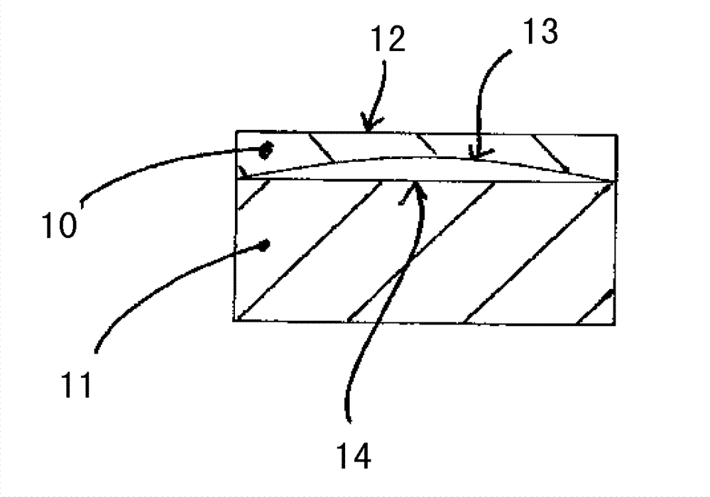
[0013] FIG. 1 shows a very simplified partial cross-section of a crankshaft bearing of a crankshaft, not shown, with a sectional direction in the axial direction of the crankshaft bearing, wherein in FIG. A cross-section and a sectional view of a section of the internal combustion engine cylinder crankcase 11 adjoining the lower bearing shell 10 . The lower bearing shell 10 , shown in axial cross-section in FIG. 1 , has a bearing shell running surface 12 which adjoins the crankshaft to be supported with play. ...


PUM


Abstract

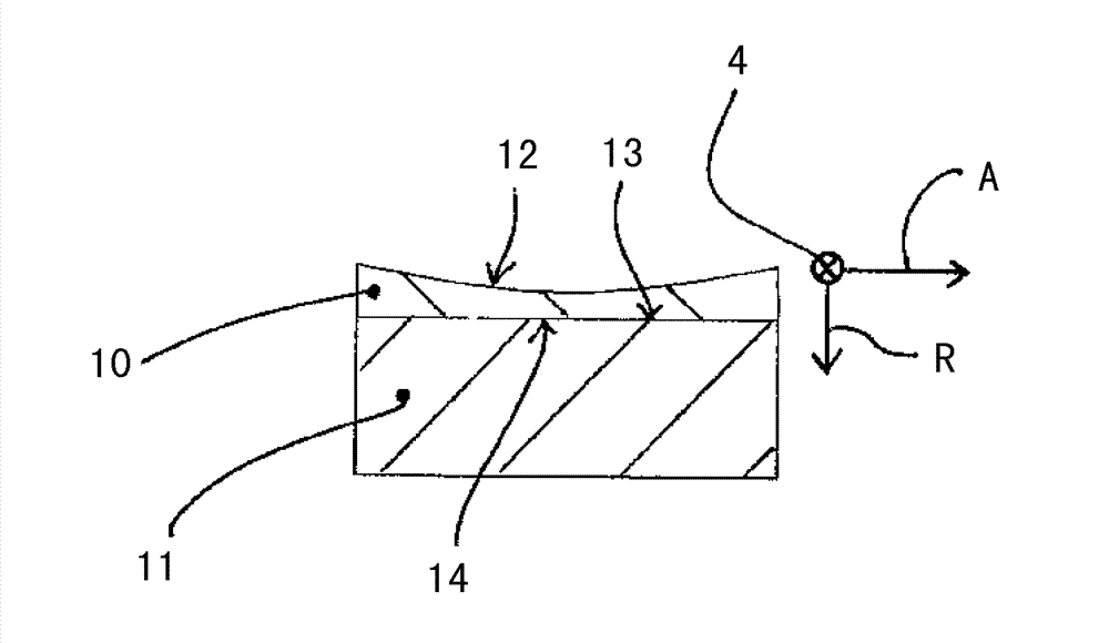
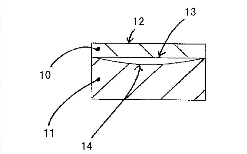
The invention relates to a bearing arrangement for a crankshaft of an internal combustion engine, comprising a sliding bearing formed by bearing shells, wherein a back (13) of a bearing shell (10) adjoins a cylinder crankcase (11) of the internal combustion engine and a bearing face (12) of said bearing shell adjoins the crankshaft to be mounted, wherein either the bearing face (12) or the back (13) of the bearing shell or a surface (14) of the cylinder crankcase (11) which adjoins the back (13) of the bearing shell has a concave shape.

Description

technical field [0001] The invention relates to a crankshaft bearing of a crankshaft of an internal combustion engine according to the preamble of claim 1 . Background technique [0002] The crankshaft bearing of the crankshaft is often also referred to as the main bearing and serves for supporting and supporting the crankshaft in the cylinder crankcase of the internal combustion engine. Crankshaft bearings generally consist of plain bearings consisting of several bearing shells, which are accommodated in the base bore of the cylinder crankcase. The base hole of the cylinder crankcase is lined with the bearing shell of the sliding bearing. The base hole is generally formed by a so-called bearing seat and a so-called bearing cover. The bearing seat is part of the cylinder crankcase, and the bearing cover is also a part of the cylinder crankcase. . The plain bearings of this crankshaft bearing are oil-lubricated in order to ensure the least possible wear of the crankshaft be...

Claims


Application Information

Patent Timeline
Patent Type & Authority Applications(China)
IPC IPC(8): F16C9/02F16C37/00
CPCF16C37/00F16C9/02F02F7/00
Inventor R.施托克N.P.朗格H.英坎普
Owner MAN ENERGY SOLUTIONS SA
Learn More