Clamping tool for cylinder-type workpiece

A workpiece clamp, cylindrical technology, applied in the direction of manufacturing tools, metal processing machinery parts, clamping, etc., can solve the problem of large clamping force, and achieve the effect of large clamping force and good centering effect.

Inactive Publication Date: 2013-05-29
徐州市恒基伟业建材发展有限公司
View PDF0 Cites 16 Cited by
  • Summary
  • Abstract
  • Description
  • Claims
  • Application Information

AI Technical Summary

Problems solved by technology

[0003] The present invention aims at the defect existing in the existing centering chuck, which is easy to cause eccentricity and affect the processing quality of the workpiece when clamping a long workpiece. The present inventi...

Method used


Image

  • Clamping tool for cylinder-type workpiece

Examples


Embodiment Construction

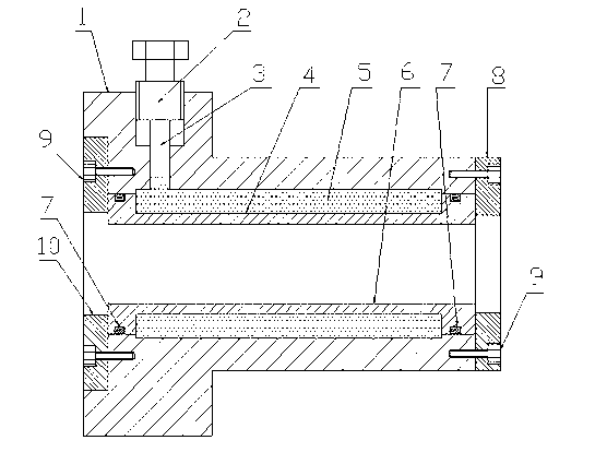
[0009] In the figure, the invention includes clamp body 1, adjusting bolt 2, piston 3, liquid plastic 5, tensioner sleeve 6, sealing ring 7, right positioning flange 8, bolt 9, left positioning flange 10, the expansion An annular groove 4 is provided on the outer circle of the tight sleeve 6, and the tension sleeve 6 is fixed in the middle through hole of the clamp body 1, and liquid plastic 5 is filled between the groove 4 and the clamp body 1, and the expansion Both ends of the tight sleeve 1 are sealed between a sealing ring 7 and the clamp body 1, and a left positioning flange 10 and a right positioning flange 8 are respectively fixed on the left and right ends of the clamp body 1 with bolts 9. The left positioning method The flange 10 and the right positioning flange 8 fix the tensioning sleeve 6 in the axial direction, and an adjusting bolt 2 is installed on the outer circle of one end of the clamp body 1, and the center part of the bottom of the adjusting bolt 2 fi...


PUM


Abstract

The invention discloses a clamping tool for a cylinder-type workpiece. When the clamping tool for the cylinder-type workpiece is worked, the cylinder-type workpiece is embedded in a center hole of a tensioning sleeve. When an adjustable bolt is tightened, a piston compresses liquid plastics. The expansion of the liquid plastics forces the inner hole to expand inwards so that the workpiece is clamped. The clamping tool for the cylinder-type workpiece has the advantages of being strong in clamping force and good in centering effects.

Description

technical field [0001] The invention relates to a clamping tool, which belongs to the clamping technology of machine tools, in particular to a cylindrical workpiece clamping tool. Background technique [0002] At present, most of the fixtures commonly used to clamp cylindrical workpieces are centering chucks. Although centering chucks have the advantage of good versatility, they are usually clamped from both ends of the workpiece when clamping the workpiece. Longer workpieces are likely to cause eccentricity and affect the processing quality of the workpiece. There is currently no better solution to this. Contents of the invention [0003] The present invention aims at the defect existing in the existing centering chuck, which is easy to cause eccentricity and affect the processing quality of the workpiece when clamping a long workpiece. The present invention provides a cylindrical workpiece clamping tool. The type workpiece clamping tool has the advanta...

Claims


Application Information

Patent Timeline
IPC IPC(8): B23Q3/00
Inventor 神凤国
Owner 徐州市恒基伟业建材发展有限公司
Why Eureka
Try Eureka