Vibrating conveyor operation detection method and detection device using the method

A vibrating conveyor and operation detection technology, applied in the direction of conveyor control devices, conveyor objects, transportation and packaging, etc., can solve problems such as hidden dangers in production, equipment damage, lack of vibrating conveyor detection, etc., to avoid sand accumulation, Protection against equipment failures

Active Publication Date: 2015-09-02
GUANGXI YUCHAI MASCH CO LTD
View PDF4 Cites 0 Cited by
  • Summary
  • Abstract
  • Description
  • Claims
  • Application Information

AI Technical Summary

Problems solved by technology

[0002] At present, the protection of the vibrating conveyor mainly includes: motor overload protection, power supply phase loss protection, etc., but if there is a problem with the driving parts of the vibrating conveyor, such as vibration caused by a broken motor belt of the vibrating machine, broken bearings, and problems with the excitation mechanism, etc. The vibrating conveyor is not working normally, and the materials in the vibrating conveyor cannot be conveyed out, but the motor is running normally, so the protection systems such as motor overload protection and power supply phase loss protection cannot detect abnormalities, so that the upstream conveying equipment cannot receive corresponding instructions and will continue to run. Conveying materials, resulting in the accumulation of materials at the vibrating conveyor in a short period of time until the motor is overloaded and detected by the motor overload protection system to stop the operation of the equipment
Especially when the vibrating conveyor is installed in pits, closed spaces, etc., and is in an unattended state, this lack of detection of the actual operation of the vibrating conveyor cannot shut down the equipment in time to avoid material accumulation, which can easily cause equipment damage , so that there is a great hidden danger in production

Method used


Image

  • Vibrating conveyor operation detection method and detection device using the method
  • Vibrating conveyor operation detection method and detection device using the method

Examples


Embodiment Construction

[0015] A specific embodiment of the present invention will be described in detail below in conjunction with the accompanying drawings, but it should be understood that the protection scope of the present invention is not limited by the specific embodiment.

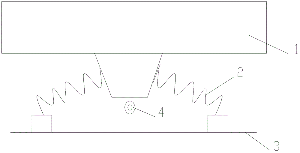
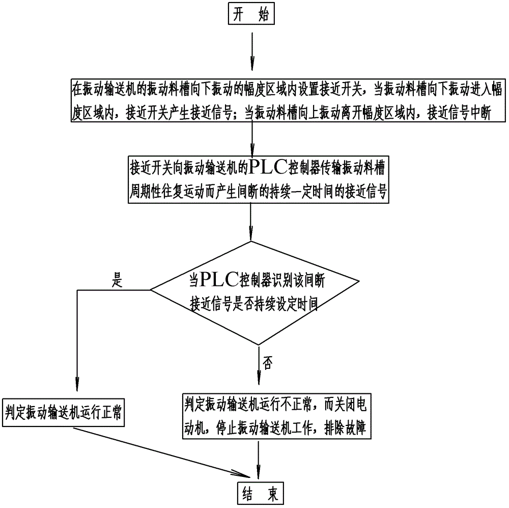
[0016] The vibrating conveyor includes: motor, exciting parts, vibrating trough and PLC controller, such as figure 1 As shown, the vibrating trough 1 is elastically supported on the vibrating conveyor base 3 by the spring 2, and the motor (not shown in the figure) drives the vibrating part (not shown in the figure) to perform periodic reciprocating motion, thereby driving the vibrating material The tank 1 performs periodic reciprocating motion, and the PLC controller (not shown in the figure) is connected with the motor. The operation detection device of the vibrating conveyor includes: a proximity switch 4 arranged in the range of the downward vibration of the vibrating material tank 1, close to The signal output end of t...


PUM


Abstract

The invention discloses a vibrating conveyer operation detection method and a detection device using the vibrating conveyer operation detection method. According to the vibrating conveyer operation detection method, an approach switch is arranged in an amplitude range of downward vibration of a vibrating material groove, a signal output end of the approach switch is connected with a programmable logic controller (PLC), discontinuous approach signals which are generated by periodic reciprocating motion of the vibrating material groove are transmitted to the PLC through the approach switch, abnormal work of a vibrating conveyer caused by the facts such as a broken motor belt of the vibrating conveyer, a broken bearing, a problem of a shock excitation mechanism can be detected, accumulation of sand in the vibrating conveyer and pits is avoided, and equipment faults are prevented from worsening.

Description

technical field [0001] The invention relates to the field of vibrating conveyors, in particular to a method for detecting the operation of a vibrating conveyor and a detecting device using the method. Background technique [0002] At present, the protection of the vibrating conveyor mainly includes: motor overload protection, power supply phase loss protection, etc., but if there is a problem with the driving parts of the vibrating conveyor, such as vibration caused by a broken motor belt of the vibrating machine, broken bearings, and problems with the excitation mechanism, etc. The vibrating conveyor is not working normally, and the materials in the vibrating conveyor cannot be conveyed out, but the motor is running normally, so the protection systems such as motor overload protection and power supply phase loss protection cannot detect abnormalities, so that the upstream conveying equipment cannot receive corresponding instructions and will continue to run. Conveying mater...

Claims


Application Information

Patent Timeline
Patent Type & Authority Patents(China)
IPC IPC(8): B65G43/08
Inventor 禤毅覃显亮李寿礼尹国平
Owner GUANGXI YUCHAI MASCH CO LTD
Why Eureka
Try Eureka