Partition stirring dry type anaerobic fermentation system

A technology of dry anaerobic fermentation and stirring components, which is applied in the field of partitioned dry anaerobic fermentation system, which can solve the problems of material viscosity, moisture content change, high installed power, and inconvenient maintenance, so as to save energy and reduce energy consumption. The effect of low consumption and convenient maintenance

Active Publication Date: 2021-12-21
SHENYANG EVERBRIGHT ENVIRONMENTAL PROTECTION GRP
View PDF19 Cites 0 Cited by
  • Summary
  • Abstract
  • Description
  • Claims
  • Application Information

AI Technical Summary

Problems solved by technology

[0004] However, the design of the above-mentioned stirring device, whether it is a mechanical stirring device, a pneumatic stirring assembly, a liquid spray stirring device or a different combination of various devices, is based on the fermentation tank as a whole. Material viscosity, moisture content and other indicators will change, and the stirring effect of the above-mentioned device needs to be further improved
[0005] In addition, in the anaerobic fermentation process, the heating and heat preservation control of the fermentation device is also very important, but the fermentation device in the prior art regards the fermentation tank as a whole for heat preservation and heating, resulting in high energy consumption and large heat loss
The main product of dry anaerobic fermentation equipment is biogas, so the form of feeding equipment needs to ensure the sealing effect of the feeding end, but the existing structures such as screw conveying and hydraulic plunger pumps are inconvenient to maintain and expensive, and the installed power is high

Method used


Image

  • Partition stirring dry type anaerobic fermentation system
  • Partition stirring dry type anaerobic fermentation system
  • Partition stirring dry type anaerobic fermentation system

Examples


Embodiment Construction

[0050] The present invention will be described in further detail below in conjunction with the accompanying drawings.

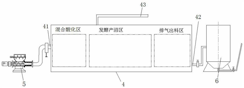
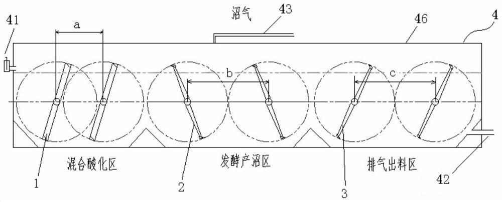
[0051] Such as Figure 1-27 Shown, the present invention comprises insulated box body 4, feeding mechanism 5 and a plurality of stirring components, wherein as figure 1 As shown, one end of the insulated box 4 is connected to the feeding mechanism 5 through a feed pipe 41, and the other end is connected to a discharge tank 6 through a discharge pipe 42, and an exhaust pipe is provided on the upper side of the insulated box 4. 43. The interior of the insulation box 4 is divided into a mixed acidification area, a fermentation methane production area and an exhaust discharge area, such as figure 2 As shown, the mixed acidification zone is provided with a first stirring assembly 1, and the first stirring assembly 1 includes a plurality of first rotating shafts, and each first rotating shaft is provided with a plurality of sets of first paddle frames, and the fi...


PUM

PropertyMeasurementUnit
thicknessaaaaaaaaaa

Abstract

The invention relates to a partition stirring dry type anaerobic fermentation system, which comprises a heat preservation box body, a feeding mechanism and a plurality of stirring assemblies; the interior of the heat preservation box body is divided into a mixed acidification area, a fermentation biogas production area and an exhaust discharging area; the mixed acidification area is provided with a first stirring assembly; furthermore, the first stirring assembly is provided with a first paddle frame; the fermentation biogas production area is provided with a second stirring assembly; the second stirring assembly is provided with a second paddle frame; the end part of the second paddle frame is provided with an inclined wing plate; the interior of the second paddle frame is provided with a mud guide plate; the exhaust discharging area is provided with a third stirring assembly; the third stirring assembly is provided with a third paddle frame; a plurality of air guide rods are arranged in the third paddle frame; a warming heating pipe and a heat preservation heating pipe are arranged in the wall of the heat preservation box body; the warming heating pipe is arranged on the outer side of the mixed acidification area; and the heat preservation heating pipe is arranged on the outer sides of the fermentation biogas production area and the exhaust discharging area. By adopting the partition stirring design, the energy consumption is effectively reduced while the fermentation effect is ensured.

Description

technical field [0001] The invention relates to the field of anaerobic fermentation equipment, in particular to a zone-stirred dry anaerobic fermentation system. Background technique [0002] Anaerobic fermentation can be divided into wet anaerobic fermentation and dry anaerobic fermentation according to the solid content (TS) of the material. Dry anaerobic fermentation refers to organic solid waste with a solid content of 20% to 40%. Anaerobic fermentation treatment process for raw materials. Compared with wet anaerobic fermentation technology, dry anaerobic fermentation has many obvious advantages, such as: 1. The reactor is small in size and occupies a small area; 2. The volumetric gas production rate is high and the heating energy consumption is low; 3. The total methane loss is low; 4. Less water consumption, there will be no problems such as scum and solid-liquid separation in wet fermentation; 5. Post-processing is easy, biogas residue can be used for organic fertili...

Claims


Application Information

Patent Timeline
Patent Type & Authority Applications(China)
IPC IPC(8): C12M1/02C12M1/107C12M1/34C12M1/38C12M1/12C12M1/20C12M1/00C02F11/04
CPCC12M21/04C12M23/48C12M23/34C12M27/06C12M41/18C12M41/12C12M45/02C12M45/06C12M45/20C12M21/16C12M29/20C12M45/04C02F11/04Y02E50/30
Inventor 张晓光刘中军高有清刘笑宇
Owner SHENYANG EVERBRIGHT ENVIRONMENTAL PROTECTION GRP
Why Eureka
Try Eureka