Determining dipper geometry

A bucket and rope technology, applied in the field of bucket geometry, can solve problems such as unavoidable

Active Publication Date: 2013-05-29
JOY GLOBAL SURFACE MINING INC
View PDF8 Cites 4 Cited by
  • Summary
  • Abstract
  • Description
  • Claims
  • Application Information

AI Technical Summary

Problems solved by technology

If the control system of the industrial machine is not properly calibrated for the geometry of the installed bucket, the industrial

Method used


Image

  • Determining dipper geometry
  • Determining dipper geometry
  • Determining dipper geometry

Examples


Embodiment Construction

[0013] Before any embodiments of the invention are explained in detail, it is to be understood that the invention is not limited by its references to the details of construction and arrangement of components set forth in the following description or illustrated in the following drawings. The invention is capable of other embodiments and of being practiced or carried out in various ways. Also, it is to be understood that the terminology and terminology used herein are for the purpose of description and should not be regarded as limiting. The use of "including," "comprising," or "having" and variations thereof herein is meant to encompass the items listed thereafter and equivalents thereof as well as additional items. The terms "mounting", "connecting" and "coupling" are used broadly and cover both direct and indirect mounting, connection and coupling. Additionally, "connected" and "coupled" are not limited to physical or mechanical connections or couplings, and may include ele...


PUM


Abstract

The invention refers to determining dipper geometry. A method of determining dipper geometry includes obtaining a first set of data associated with an industrial machine for a first orientation of the industrial machine, and obtaining a second set of data associated with the industrial machine for a second orientation of the industrial machine. The first set of data includes at least one of a first length associated with a hoist rope and a first angle associated with the hoist rope, and the second set of data includes at least one of a second length associated with the hoist rope and a second angle associated with the hoist rope. The value of the physical characteristic of the dipper is then determined based on the first set of data and the second set of data.

Description

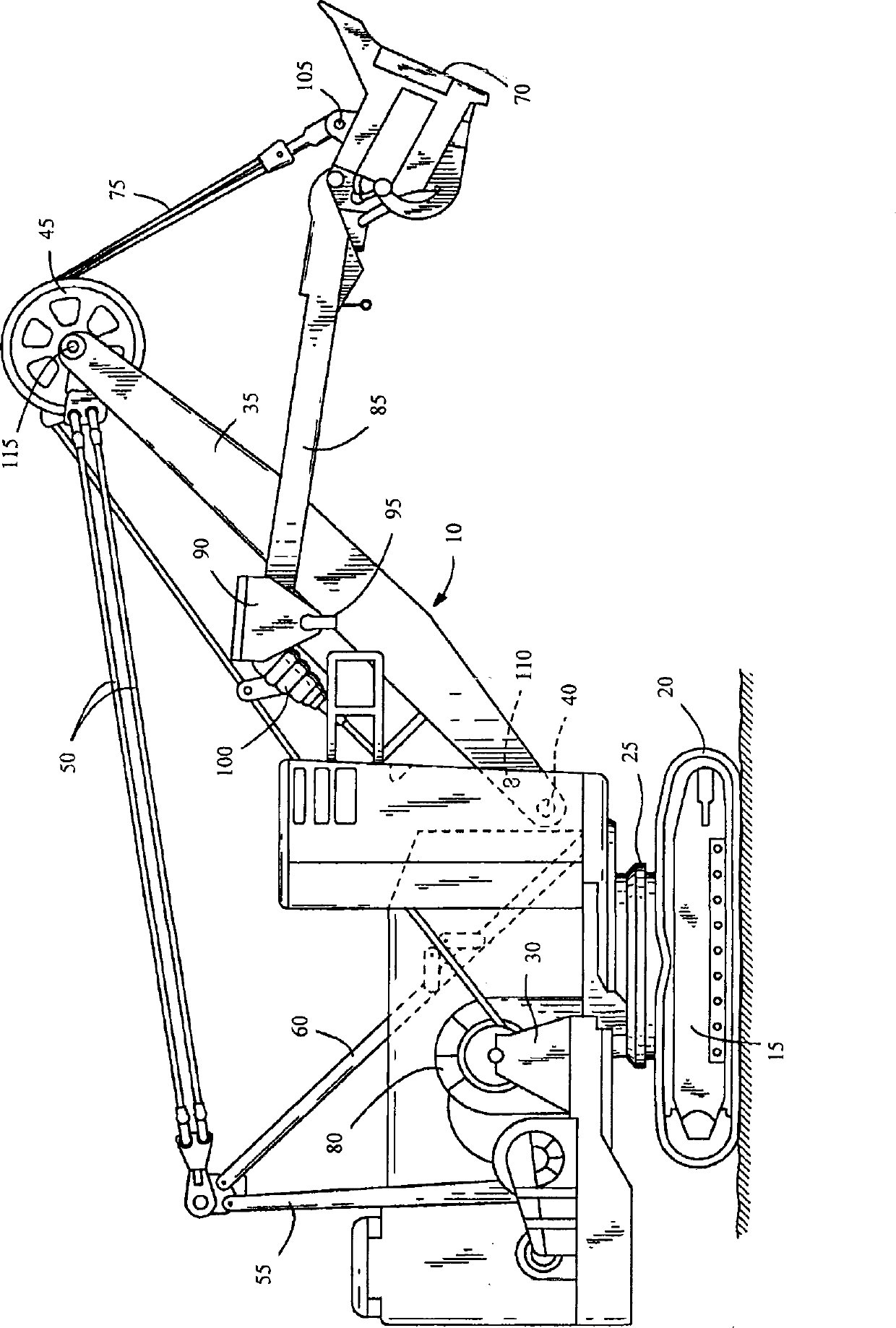
technical field [0001] The present invention relates to determining the geometry of a bucket mounted on an industrial machine such as a rope shovel. Background technique [0002] Industrial machines, such as electric rope or shovels, draglines, etc., include mounted buckets for performing excavation operations. In order to determine the location of the bucket (eg, the location of the bucket teeth), the control system associated with the industrial machine must be programmed or pre-configured taking into account the geometry of the bucket when determining its location. Such programming is typically performed manually by a service representative who manually enters into the system the dimensions associated with the bucket and other calibration parameters needed to determine the correct position of the bucket. Such a process is tedious and may vary from one industrial machine to another. For example, a particular industrial machine may be configured for use with a variety of ...

Claims


Application Information

Patent Timeline
IPC IPC(8): E02F3/46E02F3/58E02F3/60
CPCE02F3/58E02F3/60E02F3/46E02F3/308E02F3/305E02F9/2025
Inventor 韦斯利·P·泰勒
Owner JOY GLOBAL SURFACE MINING INC
Why Eureka
Try Eureka