Configurable percutaneous endoscopic gastrostomy tube

A technique of gastrostomy and endoscopy, applied in the catheter field

Active Publication Date: 2013-05-29
AVENT INC
View PDF9 Cites 5 Cited by
  • Summary
  • Abstract
  • Description
  • Claims
  • Application Information

AI Technical Summary

Problems solved by technology

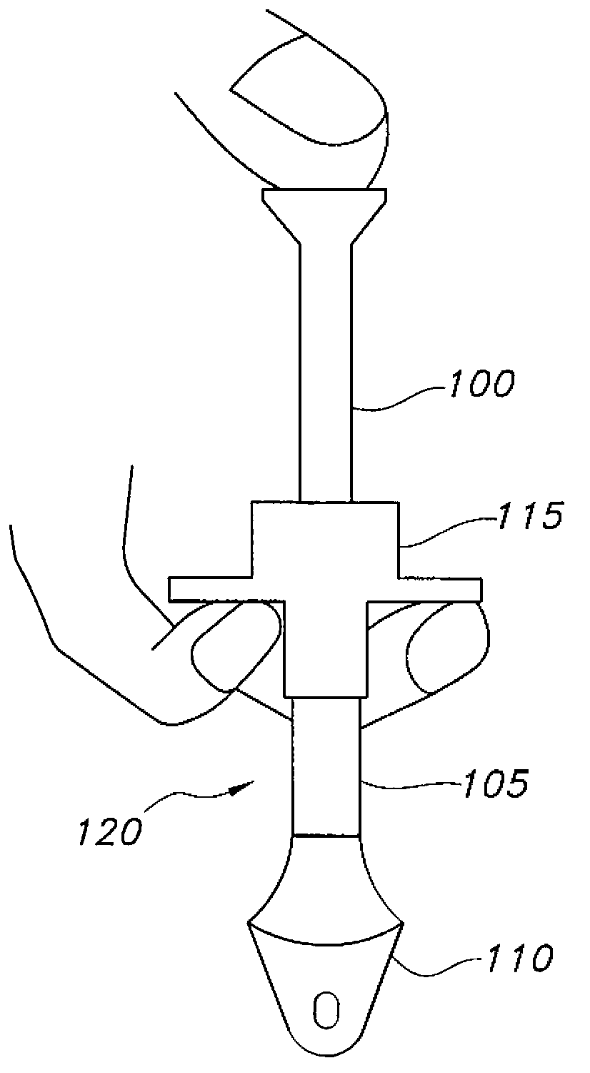
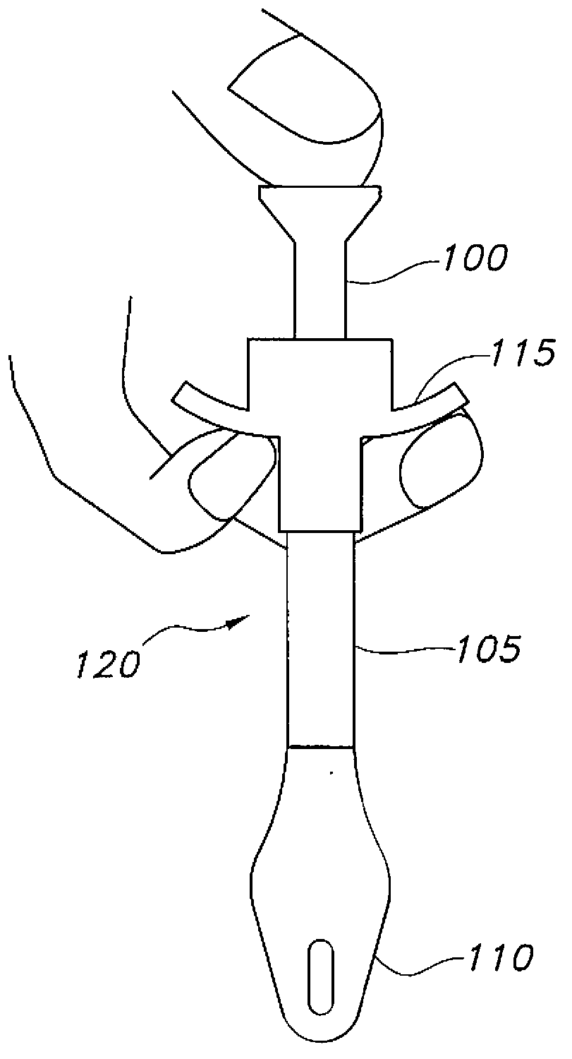
[0007] In response to the difficulties and problems discussed herein, the present invention provides an innovative PEG device that is preferably placed in the gastric cavity with direct visualization using an endoscope

Method used


Image

  • Configurable percutaneous endoscopic gastrostomy tube
  • Configurable percutaneous endoscopic gastrostomy tube
  • Configurable percutaneous endoscopic gastrostomy tube

Examples


Embodiment Construction

[0039] One or more embodiments of the present invention will now be described in detail, and multiple examples of these embodiments are shown in the accompanying drawings. It should be understood that features shown or described as part of one embodiment can be used with other embodiments to obtain yet another embodiment.

[0040] Turning now to Figure 3 of the drawings, it shows at 200 a configurable PEG device (also referred to as "C-PEG" or "C-PEG device"). The device 200 includes a flexible shaft 202 (also referred to as a "feeding tube" or "catheter"), which has a first or distal end 204 that is indwelled, and a second or proximal end 206 that remains outside the patient's body, and from The first end 204 extends to the longitudinal axis “LA” of the second end 206. The shaft 202 defines a cavity (not shown) that serves as a channel for feeding solutions and / or medications. The shaft 202 includes an expandable retainer 208 at a first end 204 of the shaft 202, the retainer 2...


PUM


Abstract

A configurable percutaneous endoscopic gastrostomy tube includes a shaft having a distal end and a proximal end. The shaft defines a lumen therethrough for passage of a feeding solution or medicine. An expandable retainer is located on the shaft, the retainer having a deployed position and an insertion position. The tube includes a releasable lock for maintaining the expandable retainer in its deployed position, the releasable lock located on the shaft proximal to the expandable retainer. A flexible sheath surrounds the expandable retainer, the sheath being generally loose around the retainer when the retainer is in an insertion position and the sheath being generally snug against an exterior surface of the retainer when the retainer is in a deployed position.

Description

Technical field [0001] The present invention relates to a catheter, such as a feeding tube, and their placement in a patient. Background technique [0002] In many cases, a catheter needs to be inserted into a body cavity to achieve the desired medical purpose. A more common situation is to supply nutrient solutions or drugs directly into the stomach or intestines. An incision is made in the wall of the stomach or intestine, and the catheter is inserted through the incision. Such surgical incisions and / or operations to create incisions are often referred to as "ostomy". The feeding solution can be injected through a catheter to directly provide nutrients to the stomach or intestines (ie enteral feeding). Over the years, people have developed a variety of different enteral feeding catheters, including those with a "low profile" relative to the part of the catheter on the patient's skin, and those with more traditional or non-low profile configurations. catheter. These percuta...

Claims


Application Information

Patent Timeline
Patent Type & Authority Applications(China)
IPC IPC(8): A61J15/00
CPCA61B17/3415A61M2205/0227A61M25/1002A61J15/0015A61M29/02A61B2019/4836A61J15/00A61M25/01A61M39/08A61J15/0042A61J15/0038A61M25/1011A61M2025/1013A61B17/29A61M13/003A61M25/09
Inventor K-M·泰A·S·巴格威尔A·T·贝克E·A·赖卡特P·A·肖尔
Owner AVENT INC
Why Eureka
Try Eureka