Pneumatic tire

A technology of pneumatic tires and tires, which is applied to tire parts, tire edge, transportation and packaging, etc., can solve the problems of durability decline, achieve the effect of improving ride comfort, increasing lateral stiffness, and reducing longitudinal stiffness

Active Publication Date: 2015-07-22
TOYO TIRE & RUBBER CO LTD
View PDF7 Cites 0 Cited by
  • Summary
  • Abstract
  • Description
  • Claims
  • Application Information

AI Technical Summary

Problems solved by technology

In this way, if the end of the carcass ply exceeds the outer end in the tire radial direction of the bead apex, strain may be concentrated near the shoulder, resulting in a decrease in durability.

Method used


Image

  • Pneumatic tire
  • Pneumatic tire
  • Pneumatic tire

Examples


Embodiment approach

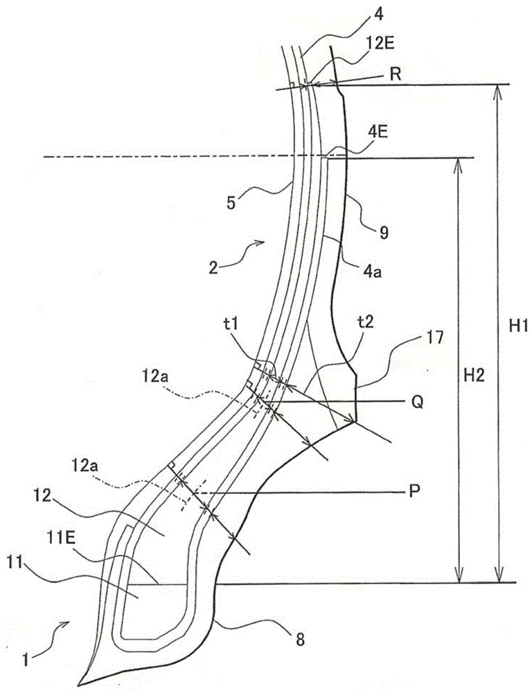
[0037] In the above embodiment, an example was shown in which the rim line 7 protruding outward in the tire width direction is provided in the sidewall portion 2 near the bead portion 1 , but the rim line 7 does not have to be provided. For example, if image 3 As shown, a rim protector 17 protruding outward in the tire width direction may also be provided on a portion of the sidewall portion 2 close to the bead portion 1 . The rim protector 17 is an annular rib extending in the tire circumferential direction and protruding outward in the width direction of the tire for preventing damage to the rim. In the case where the rim protector 17 is provided, at the apex position of the rim protector 17, the thickness of the bead filler 12 is the thickness t2 of the rubber from the ply cord of the outermost carcass ply 4a to the tire outer surface. The proportion of t1 is 10~30%. For example, at the apex position of the rim protector 17, the thickness t1 of the bead filler 12 is 1.7 ...

Embodiment 1 and Embodiment 2

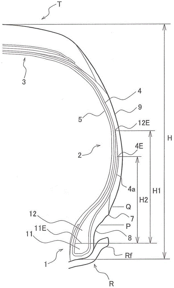
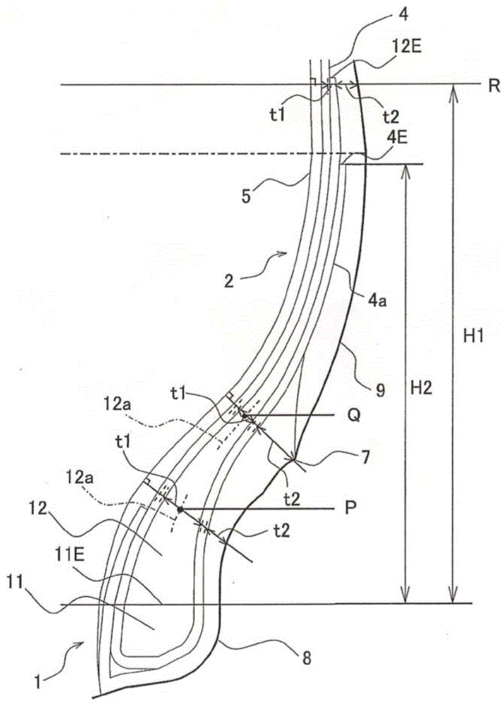
[0049] A pneumatic tire was manufactured in which the sectional height H1 of the bead filler 12 was 50% of the tire sectional height H, and the thickness t1 of the bead filler 12 was 20 mm from the radially outer end of the bead core 11 to the outer side in the tire radial direction. The position Q of 1.7 mm is 1.7 mm, and the turned-up end 4E of the carcass ply 4 terminates closer to the inner side in the tire radial direction than the outer peripheral end 12E of the bead filler 12 . Using this pneumatic tire, the above-mentioned evaluation was performed, and the results are shown in Table 1.


PUM


Abstract

The invention provides a pneumatic tire which limits the mass of the tire while improving the driving stability and comfort. The pneumatic tire comprises a bead core (11) embedded in a bead part (1), a bead filler (12) arranged at the tire radial outside of the bead core (11), a carcass ply (4) which can be wound up around the bead core (11) from internal towards external, and side wall rubber (9) which constitutes an external wall of a tire. The section height (H1) of the bead filler (12) with a tire radical outer end (11E) of the bead core (11) as a reference constitutes 50 to 70% of tire section height (H). The thickness (t1) of the bead filler (12) at the position Q, which is 20mm from the tire radical outer end of the bead filler (11) to the tire radial outside, is smaller than 1.7mm, and the thickness (t1) decreases gradually towards the tire radical outside. A winding-up end (4E) of the carcass ply (4) is terminated at a position closer to the tire radical inside than a peripheral end (12E) of the bead filler.

Description

technical field [0001] The present invention relates to a pneumatic tire comprising a bead core embedded in a bead portion, a bead filler arranged outside the bead core in the tire radial direction, and a bead filler wound around the bead core from inside to outside. The carcass ply and the sidewall rubber that make up the outer wall of the tire. Background technique [0002] In recent years, due to the increase in vehicle fuel costs, the demand for lightweight tires has further increased. In order to reduce the weight of the tire, it is effective to reduce the mass of the sidewall rubber to make the thickness of the sidewall thin. However, if the sidewall is thinned, the lateral rigidity of the tire tends to decrease, resulting in a decrease in driving stability. [0003] In order to reduce the mass of the sidewall rubber and increase the lateral rigidity of the tire to improve driving stability, it is considered to increase the size of the bead filler. However, if the be...

Claims


Application Information

Patent Timeline
Patent Type & Authority Patents(China)
IPC IPC(8): B60C15/04
Inventor 西川修一
Owner TOYO TIRE & RUBBER CO LTD
Why Eureka
Try Eureka