Corrugated steel plate composite shear wall

A combination of shear wall and steel plate technology, applied in the direction of walls, building components, buildings, etc., can solve the problems of rapid decline in bearing capacity of corrugated steel plate walls, troublesome processing and on-site installation, unfavorable rapid construction, etc., to eliminate adverse effects, Facilitate rapid construction and improve the effect of hysteresis curve pinching

Inactive Publication Date: 2012-12-26
TSINGHUA UNIV
View PDF5 Cites 27 Cited by
  • Summary
  • Abstract
  • Description
  • Claims
  • Application Information

AI Technical Summary

Problems solved by technology

[0003] There are the following deficiencies in the flat steel plate shear wall: First, the thick plate wall is not easy to buckle under the action of lateral force, the hysteretic curve is full, and the ductility and energy dissipation capacity are strong, but the amount of steel is large, so it is rarely used in engineering
[0005] In order to solve the above problems in ordinary steel plate shear walls, the inventor proposed a multi-layer steel plate composite shear wall in Chinese patent (ZL201010515879.5), which effectively improves the hysteretic curve of the thin flat steel plate wall Pinching, and the rapid decline in the bearing capacity of the corrugated steel plate wall
However, this multi-layer steel plate combined shear wall will still be affected by the vertical compressive stress during construction and use; in addition, the processing method of connecting the combined shear wall plate and the surrounding frame through C-shaped steel, processing and on-site installation More troublesome, not conducive to rapid construction

Method used


Image

  • Corrugated steel plate composite shear wall
  • Corrugated steel plate composite shear wall
  • Corrugated steel plate composite shear wall

Examples


Embodiment Construction

[0015] Attached below Figure 1~3 , The embodiment of the present invention will be described in detail.

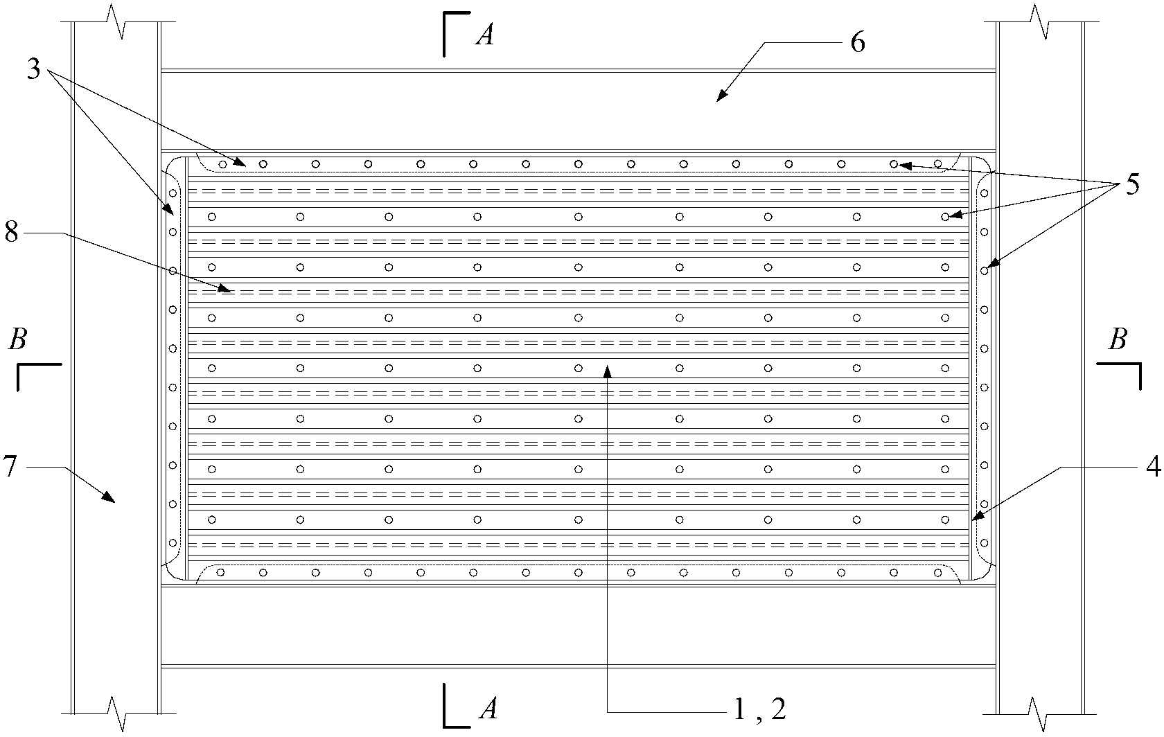
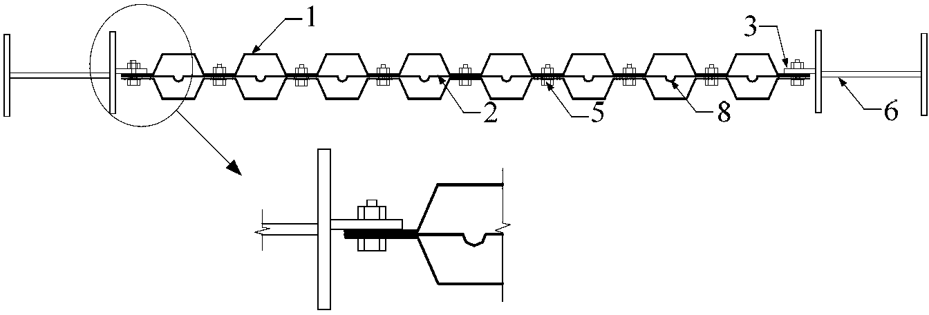
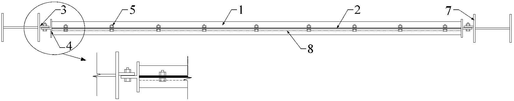
[0016] As shown in the figure, an improved composite shear wall with corrugated steel plate includes the following components:

[0017] 1-Trapezoidal corrugated steel plate;

[0018] 2-Flat steel plate with corrugation;

[0019] 3——Fish plate;

[0020] 4——T-shaped steel;

[0021] 5——High-strength bolts;

[0022] 6——Frame beam;

[0023] 7——Frame column;

[0024] 8-ripples.

[0025] An improved composite shear wall with corrugated steel plate proposed by the present invention is composed of trapezoidal corrugated steel plate (1), corrugated flat steel plate (2), fish plate (3), T-shaped steel (4), and high-strength bolts ( 5) Composed of frame beams (6) and frame columns (7).

[0026] The corrugated flat steel plate (2) is obtained by pressing the flat steel plate to form corrugations (8) every one wavelength of the trapezoidal corrugated steel plate. The composite shear wall panel is c...


PUM


Abstract

The invention relates to a corrugated steel plate composite shear wall comprising trapezoidal corrugated steel plates, a flat steel plate with corrugations, a fishplate, a T-shaped profile steel, high-strength bolts, a frame beam and a frame column, wherein the flat steel plate with the corrugations is clamped between the two trapezoidal corrugated steel plates, and the trapezoidal corrugated steel plates and the flat steel plate are connected on the wave trough parts of the trapezoidal corrugated steel plates through the high-strength bolts to form a composite shear wall plate; the flat steel plate with the corrugations is obtained by pressing to form the corrugations at intervals of the distance of one wave length of each trapezoidal corrugated steel plate on the flat steel plate; the trapezoidal corrugated steel plates and the flat steel plate are all horizontally placed; the upper edge and the lower edge of the corrugated steel plate composite shear wall are connected with the fishplate welded on the flange of the frame beam by adopting the high-strength bolts, and the left side edge and the right side edge are welded with the T-shaped profile steel. The corrugated steel plate composite shear wall provided by the invention has the advantages of high lateral resistant capability, plump hysteretic curve, industrial production, assembling type fast construction and the like without bearing vertical axial force and is a superior seismic-resisting energy-consuming member.

Description

Technical field [0001] The invention relates to an improved composite shear wall with corrugated steel plates, which belongs to the technical field of structural engineering. Background technique [0002] Compared with the traditional concrete shear wall which has high rigidity but poor ductility, the steel plate shear wall matches the rigidity and ductility of the steel frame, and has strong energy dissipation capacity. Therefore, as an excellent performance energy dissipation and shock absorption component, it is widely used Applied to high-rise structures. In terms of steel plate form, it mainly includes two types: flat steel plate shear wall and corrugated steel plate shear wall. [0003] There are the following shortcomings in the flat steel plate shear wall: First, the thick plate wall is not easy to buckle under the action of lateral force, the hysteretic curve is full, the ductility and energy consumption are strong, but the amount of steel is large, and it is rarely used ...

Claims


Application Information

Patent Timeline
Patent Type & Authority Applications(China)
IPC IPC(8): E04B2/58
Inventor 窦超郭彦林赵思远刘锋陈航
Owner TSINGHUA UNIV
Why Eureka
Try Eureka