Clearance fluid-loss test method based on oil-well pump performance testing device
The technology of a test device and test method is applied in the direction of pump test, liquid variable displacement machine, machine/engine, etc. It can solve the problems of oil well pump valve ball opening lag, reduce the fullness of the pump cavity, and increase the development cost, etc., to achieve Accurate test results, simple test steps, and reduced test costs
Inactive Publication Date: 2013-06-05
欧阳才伟
View PDF0 Cites 7 Cited by
- Summary
- Abstract
- Description
- Claims
- Application Information
AI Technical Summary
Problems solved by technology
There are two technically controversial issues about oil well pumps: one is whether the whole cylinder type oil well pump is better or the bushing type oil well pump is better; the other is whether it is better to have sand control grooves on the plunger or no sand control grooves
These gases occupy part of the volume of the pump chamber, which will reduce the fullne
Method used
View moreImage
Smart ImageViewing Examples

Examples
 PUM
 Abstract
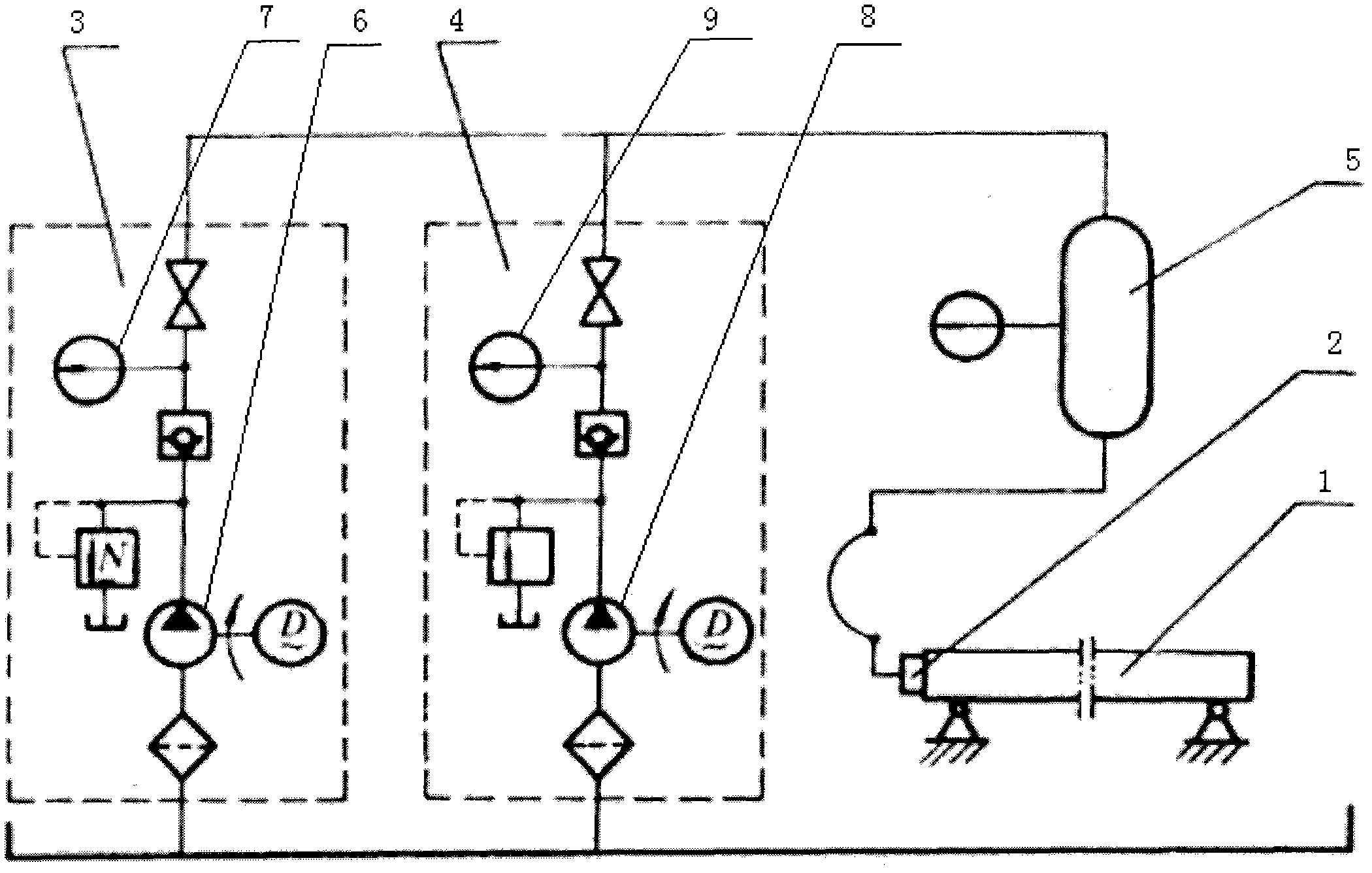
The invention discloses a clearance fluid-loss test method based on an oil-well pump performance testing device. The clearance fluid-loss test method based on the oil-well pump performance testing device includes that (a), an oil-well pump without installation of a plunger assembly is flatwise placed on a support; (b), a group of cylindrical steel ejecting rods capable of limiting the plunger assembly to be positioned at a test position is installed in a pump cylinder; (c), the plunger assembly matched with the pump cylinder is installed; (d), a pressure test joint is screwed up tightly on a pump cylinder coupling hoop; (e), a low-pressure liquid charging pump is started to charge the pump cylinder until the pump cylinder is full of diesel oil, and meanwhile the plunger assembly is also delivered to the positions of the ejecting rods by the diesel oil in a pressurized mode; (f), the low-pressure liquid charging pump is shut down, a high-pressure test pump is started, the diesel oil is continued to be filled into the pump cylinder, and meanwhile, the rising situation of a gauge hand of a pressure gauge is closely watched; and (g), when the gauge hand rises to a fluid-loss test pressure and the quantity of the diesel oil leaked from an outlet of the lower end of the pump cylinder is stable, a measuring pot is used to receive the leaked and lost diesel oil for a minute, and the quantity of the diesel oil in the measuring pot is measured. The clearance fluid-loss test method based on the oil-well pump performance testing device can be used for measuring the clearance fluid-loss quantity of the oil-well pump, and is accurate in test result, simple in test steps, speedy in test, and reduced in test cost.
Description
technical field [0001] The invention relates to a gap leakage test method based on an oil well pump performance test device. Background technique [0002] Before the 20th century, the development of oil well pump technology at home and abroad was slow, and it was not until the middle of the 20th century that the whole barrel oil well pump was studied and produced simultaneously with the bushing type oil well pump. There are two technically controversial issues about oil well pumps: one is whether the whole barrel type oil well pump is better or the bushing type oil well pump is better; the other is whether it is better to have sand control grooves on the plunger or not to have sand control grooves. Until the 1980s, due to the significant improvement of the pump efficiency of the whole barrel pump, it is generally about 10% higher than that of the bushing pump, which prolongs the service life of the plunger pump barrel pair, and can save about 40% of high-quality steel. Inst...
Claims
Login to View More Application Information
Patent Timeline
 IPC IPC(8): F04B51/00
Inventor 欧阳才伟
Owner 欧阳才伟
Features
- Generate Ideas
- Intellectual Property
- Life Sciences
- Materials
- Tech Scout
- Unparalleled Data Quality
- Higher Quality Content
- 60% Fewer Hallucinations
Learn More Browse by: Latest US Patents, China's latest patents, Technical Efficacy Thesaurus, Application Domain, Technology Topic, Popular Technical Reports.
© 2025 PatSnap. All rights reserved.Legal|Privacy policy|Modern Slavery Act Transparency Statement|Sitemap|About US| Contact US: help@patsnap.com