
Movable cavity water guide valve device of upright open type pump system

A water diversion valve, open type technology, which is applied to the components of pumping devices for elastic fluids, non-variable-capacity pumps, pumps, etc., can solve the problem of limiting the efficiency of pumping devices, inconvenient maintenance, and complex equipment structure. and other problems, to achieve the effect of saving project investment and maintenance costs, reducing auxiliary equipment, and having a reasonable and simple structure

Active Publication Date: 2014-04-02
扬州智创企业运营管理服务有限公司
View PDF6 Cites 0 Cited by
  • Summary
  • Abstract
  • Description
  • Claims
  • Application Information

AI Technical Summary

Problems solved by technology

However, since the outlet flow channel of this type of pump device adopts an open water outlet, the water surface is violently turbulent, resulting in a large loss of water kinetic energy, which limits the improvement of the efficiency of the pump device.
On the other hand, in order to keep the reverse speed of the motor from exceeding the safe range when the pump stops, the pump device needs to be equipped with a shut-off and locking device such as a flap door or a quick gate, which not only has a complex structure and is inconvenient to maintain, but also requires a lot of investment.

Method used


Image

  • Movable cavity water guide valve device of upright open type pump system
  • Movable cavity water guide valve device of upright open type pump system
  • Movable cavity water guide valve device of upright open type pump system

Examples


Embodiment Construction

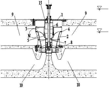
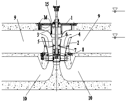
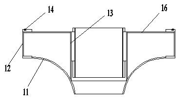
[0016] Such as figure 1 , figure 2 , image 3 , Figure 4 , Figure 5 As shown, the movable cavity water guide valve device of the vertical open pump device is composed of a fixed water guide cone 5 installed above the water pump outlet, a water pump outlet trumpet tube 2, an upper cover plate 1 of the water outlet channel, and a movable cavity guide. Water valve 3 etc. are formed, and the movable cavity water guide valve that is inverted frustum shape is set between the bell pipe of water pump outlet and the upper cover plate of the water outlet flow channel, and the bulk density of the movable cavity water guide valve is slightly greater than water. A casing 15 is arranged on the outer periphery of the pump shaft 6 of the water pump, and the casing is arranged and fixed under the upper cover plate of the water outlet flow channel, and the casing corresponds to the coaxial center of the fixed water guide cone. The movable cavity water diversion valve is a closed cavity s...


PUM


Abstract

The invention discloses a movable cavity water guide valve device of an upright open type pump system, and belongs to the technical field of hydraulic engineering. The movable cavity water guide valve device comprises a fixing water guide cone, a flared pipe of an outlet of a water pump and an upper cover plate of a water outlet flow channel, and is characterized in that a movable cavity water guide valve in the shape of an inverted frustum is arranged between the flared pipe of the outlet of the water pump and the upper cover plate of the water outlet flow channel, and is penetratingly sleeved on an outer sleeve of a pump shaft of the water pump, a curved pipe wall is arranged on the outer wall of the movable cavity water guide valve, a plane which is matched with an orifice of the flared pipe of the outlet of the water pump in a contact manner is arranged at the upper edge of the pipe wall, and the orifice of the flared pipe of the outlet of the water pump is provided with an O-shaped rubber sealing ring. The movable cavity water guide valve device has the advantages that the movable cavity water guide valve device is reasonable and simple in structure and novel in conception, the movable cavity water guide valve with the unit weight slightly larger than that of water is arranged between the flared pipe of the outlet of the water pump and the upper cover plate of the water outlet flow channel, and is used for guiding water flow at the outlet of the water pump, the head loss is obvious reduced, river closure locking can be realized when a water pump unit shuts down, accessory facilities of a pump station are reduced, and the engineering investment and the maintenance cost are saved.

Description

technical field [0001] The invention relates to equipment for a low-lift pump device, in particular to a device for shutting off a vertically installed open pump and reducing the loss of flow energy of effluent, and belongs to the technical field of water conservancy engineering. Background technique [0002] The vertically installed open pump device has the advantages of simple structure, low civil construction investment, and convenient installation and maintenance. It is especially suitable for small and medium-sized low-lift pumping stations and pumping stations with two-way pumping. However, since the water outlet channel of this type of pump device adopts an open water outlet, the water surface churned violently, resulting in a large loss of water kinetic energy, which limited the improvement of the efficiency of the pump device. On the other hand, in order to keep the reverse speed of the motor from exceeding the safe range when the pump is stopped, the pump device ne...

Claims


Application Information

Patent Timeline
Patent Type & Authority Patents(China)
IPC IPC(8): F04D29/00F04D29/46
Inventor 陆伟刚严登丰杜开连周必翠万代祥杨婷婷
Owner 扬州智创企业运营管理服务有限公司
Learn More