clutch master cylinder

A master cylinder and cylinder body technology, applied in the direction of clutches, fluid-driven clutches, non-mechanical drive clutches, etc., can solve the problems of easy wear and tear of seals, achieve the effects of easy removal, ease of damage, and improved service life

Inactive Publication Date: 2016-08-24
BEIJING JINLIAN GUOYU BRAKE PUMP
View PDF10 Cites 0 Cited by
  • Summary
  • Abstract
  • Description
  • Claims
  • Application Information

AI Technical Summary

Problems solved by technology

[0012] The present invention aims to provide a clutch master cylinder to solve the problem in the prior art that the seal often rubs against the cylinder body so that the seal is easy to wear

Method used


Image

  • clutch master cylinder
  • clutch master cylinder
  • clutch master cylinder

Examples


Embodiment Construction

[0035] It should be noted that, in the case of no conflict, the embodiments in the present application and the features in the embodiments can be combined with each other. The present invention will be described in detail below with reference to the accompanying drawings and examples.

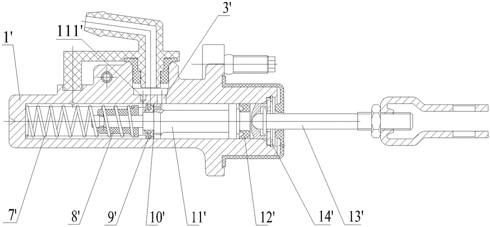
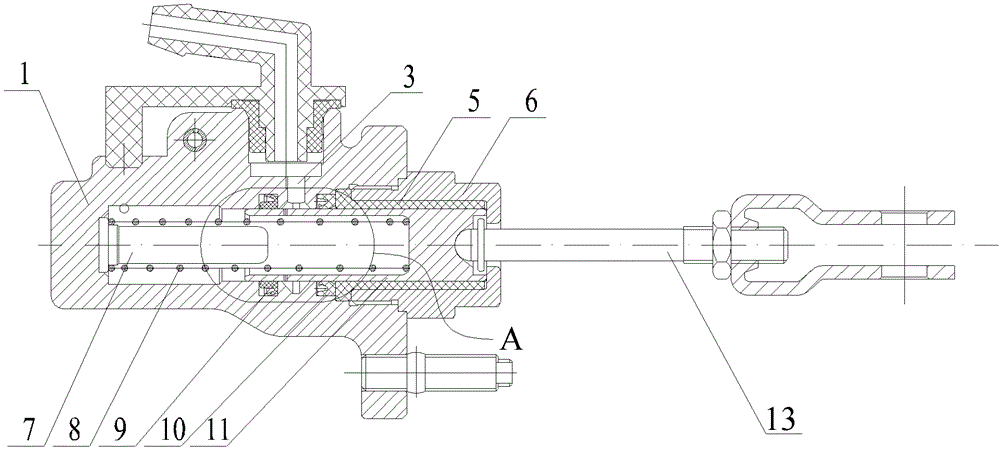
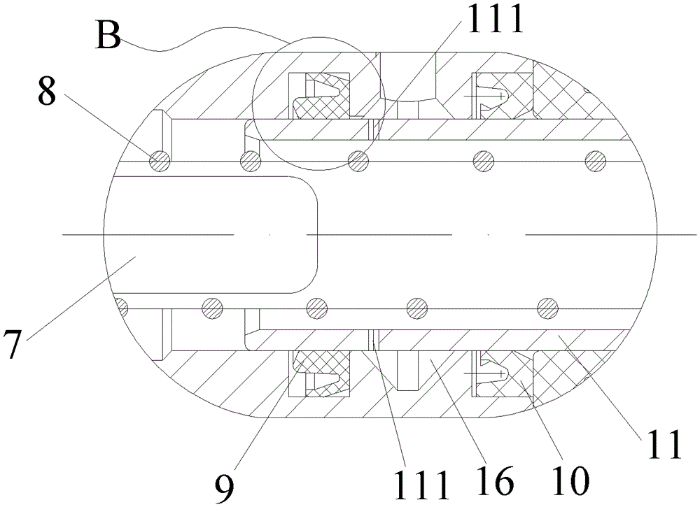
[0036] figure 2 shows a schematic cross-sectional view of an embodiment of a clutch master cylinder according to the invention, image 3 show figure 2 Partial enlarged schematic diagram of A of the clutch master cylinder. see in conjunction Figure 2 to Figure 3 , It can be seen from the figure that the clutch master cylinder of this embodiment includes: a master cylinder body 1 , a first cup 9 , a second cup 10 , a piston 11 and a return spring 8 . Wherein, the inside of the master cylinder body 1 has a cavity, the master cylinder body 1 is provided with an oil inlet 3, and the master cylinder body 1 has a first annular groove and a second annular groove located on both sides of the oil ...


PUM


Abstract

The invention provides a clutch main cylinder which comprises a main cylinder main body, a first leather cup, a second leather cup, a piston and a return spring. A cavity body is arranged inside the main cylinder main body. An oil inlet is formed in the main cylinder main body which is provided with a first ring-shaped groove and a second ring-shaped groove, wherein the first ring-shaped groove and the second ring-shaped groove are arranged at two sides of the oil inlet. The first leather cup is arranged in the first ring-shaped groove. The second leather cup is arranged in the second ring-shaped groove. The piston is arranged on the inner sides of the first leather cup and the second leather cup. A first end of the piston is connected with a push rod at a first end of the main cylinder main body. An inner hole is formed in the piston and opens towards a second end of the piston. A compensation hole is formed in the side wall which is provided with the inner hole on the piston. When the piston is located at the first end of the main cylinder main body, the compensation hole is located between the first leather cup and the second leather cup and is communicated with the oil inlet. A first end of the return spring is fixed at a second end of the main cylinder main body. A second end of the return spring is contained in the inner hole of the piston. The clutch main cylinder effectively solves the problems that due to the fact that a sealing part frequently rubs the cylinder body, the sealing part is prone to abrasion.

Description

technical field [0001] The invention relates to the field of clutch master cylinders of motor vehicles, in particular to a clutch master cylinder. Background technique [0002] The clutch master cylinder of a motor vehicle is installed on the front wall of the car and connected to the clutch pedal. Its main function is that when the car needs to shift gears, step on the pedal, and the clutch master cylinder builds up a certain pressure, which is transmitted to the clutch through the oil pipe. Slave cylinder, clutch slave cylinder receives the liquid flow and pressure delivered by the master cylinder, directly or indirectly pushes the release bearing to separate the clutch. [0003] figure 1 shows the clutch master cylinder in the prior art, such as figure 1 As shown, the oil inlet 3' of the clutch master cylinder in the prior art communicates with the liquid storage chamber of the brake master cylinder, and an aluminum alloy piston 11' is housed in the master cylinder body...

Claims


Application Information

Patent Timeline
Patent Type & Authority Patents(China)
IPC IPC(8): F16D25/12
Inventor 秦丽荣张国玉
Owner BEIJING JINLIAN GUOYU BRAKE PUMP
Why Eureka
Try Eureka