
Buried pipe ground temperature measuring device and measuring methods

A measurement method and technology for buried pipes, which are applied in directions such as thermometers that give average/integrated values, can solve the problems of large test point spacing, high test cost, rough initial temperature, etc., so as to improve test accuracy and reduce test cost. low effect

Inactive Publication Date: 2013-06-05
湖南凌天科技有限公司
View PDF4 Cites 20 Cited by
  • Summary
  • Abstract
  • Description
  • Claims
  • Application Information

AI Technical Summary

Problems solved by technology

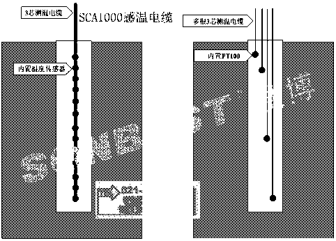
[0006] In these two patents, a certain number of temperature sensors are arranged inside or outside the buried tube heat exchange tube, and the temperature data of different temperature sensors can be recorded to obtain a rough initial temperature of each layer of soil. The main disadvantage is that : If the number of temperature sensors is small, the distance between the test points is large, and the test results must be rough; if the number of temperature sensors is large, the number of temperature cables must be large, the test cost is high, the construction is complicated, and because The error of the temperature sensor is inconsistent, some are positive temperature difference and some are negative temperature difference, which has a more obvious impact on the final result
However, this method can still only arrange a limited number of temperature sensors, and the accuracy of the test is still limited. If a large number of temperature sensors are deliberately arranged, the cost will still be high

Method used


Image

  • Buried pipe ground temperature measuring device and measuring methods
  • Buried pipe ground temperature measuring device and measuring methods
  • Buried pipe ground temperature measuring device and measuring methods

Examples


Embodiment 1

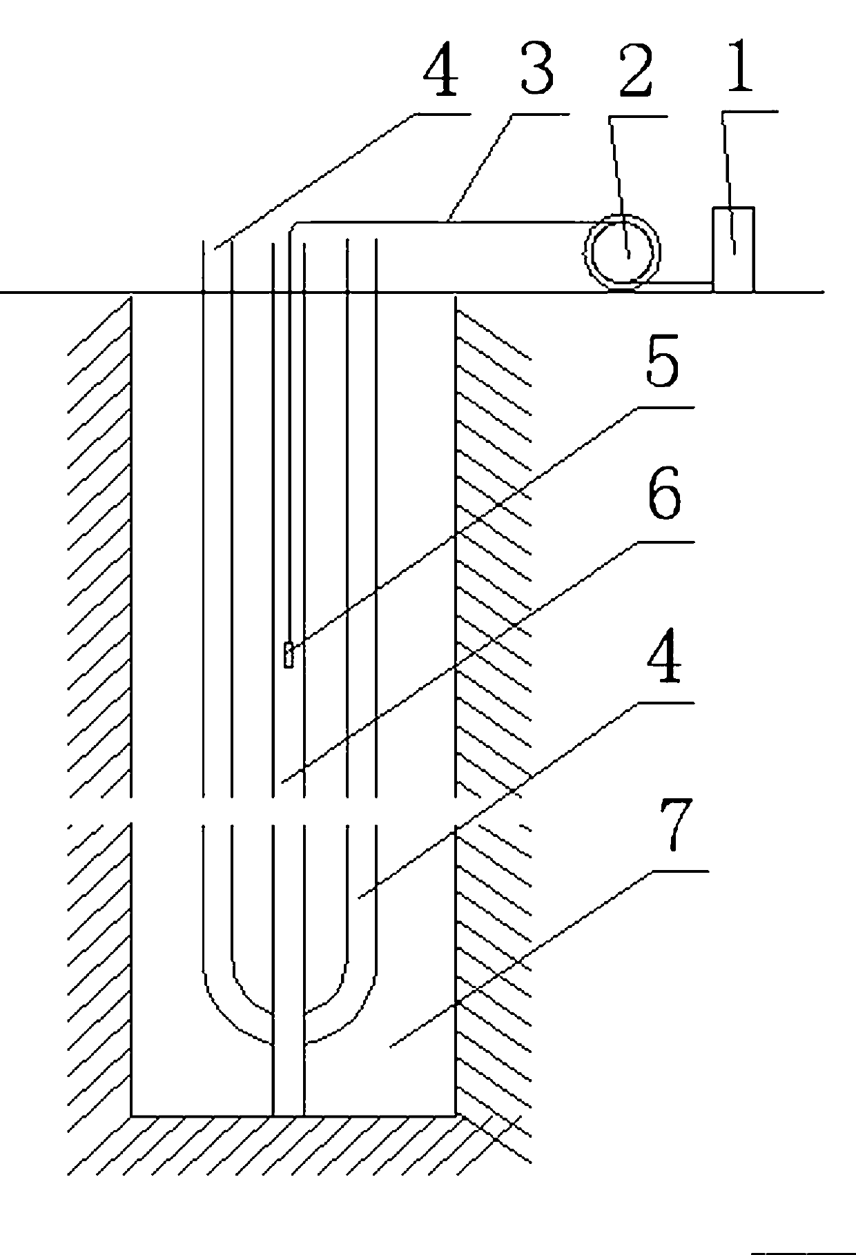
[0044] Embodiment one: if figure 1 As shown, the first method for measuring the ground temperature of the buried pipe is characterized in that it comprises the following steps:

[0045] a. Prepare a temperature measuring tube 6 equal in length to the heat exchange tube 4, and put the temperature sensor 5 and the cable 3 connected thereto into the temperature measuring tube 6 in advance;

[0046] b. After the drilling 7 is completed, put the temperature measuring tube 6 and the heat exchange tube 4 side by side into the test hole 7, the temperature sensor 5 is located at the lowermost end of the temperature measuring tube 6, backfill the tube, and let it stand for at least 48 hours;

[0047] c. Connect the cable 3 of the temperature sensor 5 and the data logger 1, and start the data logger 1;

[0048] d. Move the temperature sensor 5 upwards at a constant speed along the direction of the pipeline in the temperature measuring tube 6, and observe whether the data recorder 1 re...

Embodiment 2

[0053] Embodiment two: if figure 1 As shown, the first method for measuring the ground temperature of the buried pipe is characterized in that it comprises the following steps:

[0054] a. Prepare a temperature measuring tube 6 equal in length to the heat exchange tube 4;

[0055] b. After the drilling 7 is completed, put the temperature measuring tube 6 and the heat exchange tube 4 side by side into the test hole 7, backfill the tube, and let it stand for at least 48 hours;

[0056] c. Put the temperature sensor 5 into the top inlet of the temperature measuring tube 6, and start the data recorder 1;

[0057] d. Move the temperature sensor 5 downward at a constant speed along the direction of the pipeline in the temperature measuring tube 6, and observe whether the data recorder 1 records and stores the temperature data normally;

[0058] e. When the temperature sensor 5 reaches the bottom of the temperature measuring tube 6, stop recording and storing the temperature data;...

Embodiment 3

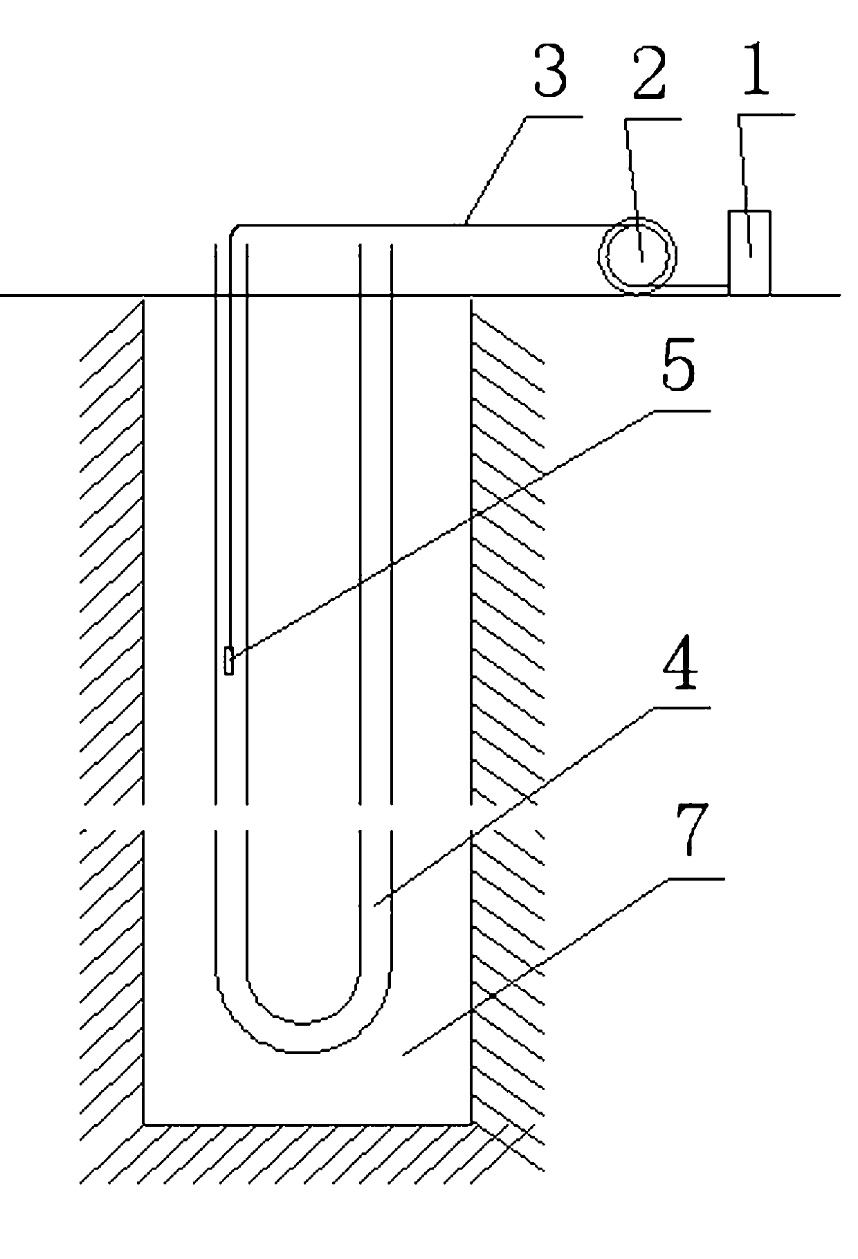
[0062] Embodiment three: as figure 2 As shown, the second method for measuring the ground temperature of the buried pipe is characterized in that it includes the following steps:

[0063] a. Thread the temperature sensor 5 and the cable 3 connected thereto into the heat exchange tube 4 in advance;

[0064] b. After the drilling 7 is completed, put the heat exchange tube 4 together with the temperature sensor 5 and the cable 3 into the test hole 7. The temperature sensor 5 is located at the bottom guide of the buried tube heat exchanger 4, and backfill Bury the pipe and let it stand for at least 48 hours;

[0065] c. Connect the cable 3 of the temperature sensor 5 and the data logger 1, and start the data logger 1;

[0066] d. Move the temperature sensor 5 upward at a constant speed along the direction of the pipe in the heat exchange pipe 4, and observe whether the data recorder 1 records and stores the temperature data normally;

[0067] e. When the temperature sensor 5 r...


PUM


Abstract

The invention discloses a buried pipe ground temperature measuring device and three methods for measuring buried pipe ground temperature. The device is suitable for an initial ground temperature test of a ground source heat pump buried pipe of a rock-soil body heat physical property test and for long-term monitoring buried pipe project dynamic temperature. The key technical scheme includes that one temperature sensor is used for measuring temperatures of multiple points, is placed into a heat exchange pipe or a heat measuring pipe, can be moved along the heat exchange pipe or the heat measuring pipe, and at the same time, measures the temperatures. Therefore, only one temperature sensor can complete a temperature measuring task in a whole testing hole. Data recording interval time of a temperature data recorder is adjusted, or moving speed of the temperature sensor is adjusted, or the data recording interval time of the temperature data recorder and the moving speed of the temperature sensor are adjusted simultaneously, and the number of temperature measuring points which are required at will can be simply achieved, and therefore the testing precision requirement is guaranteed.

Description

technical field [0001] The invention relates to the field of geotechnical engineering investigation, in particular to an initial ground temperature testing device and a testing method for a ground source heat pump buried pipe for testing the thermophysical properties of rock and soil, and a ground temperature testing device and a testing method for long-term monitoring of the dynamic temperature of a buried pipe project. [0002] Background technique [0003] In the thermal response test of ground source heat pump, the initial temperature of rock and soil mass is an important design parameter and must be tested. As we all know, it is very important to accurately express the soil temperature, because the temperature difference between the ground and the circulating water in the buried heat exchange tube is the driving force for heat transfer. In order to ensure the economic and safe operation of the ground source heat pump system in the future, the results of analysis and ca...

Claims


Application Information

Patent Timeline
IPC IPC(8): G01K3/02
Inventor 李明
Owner 湖南凌天科技有限公司
Learn More